OPERATION
Checking Float
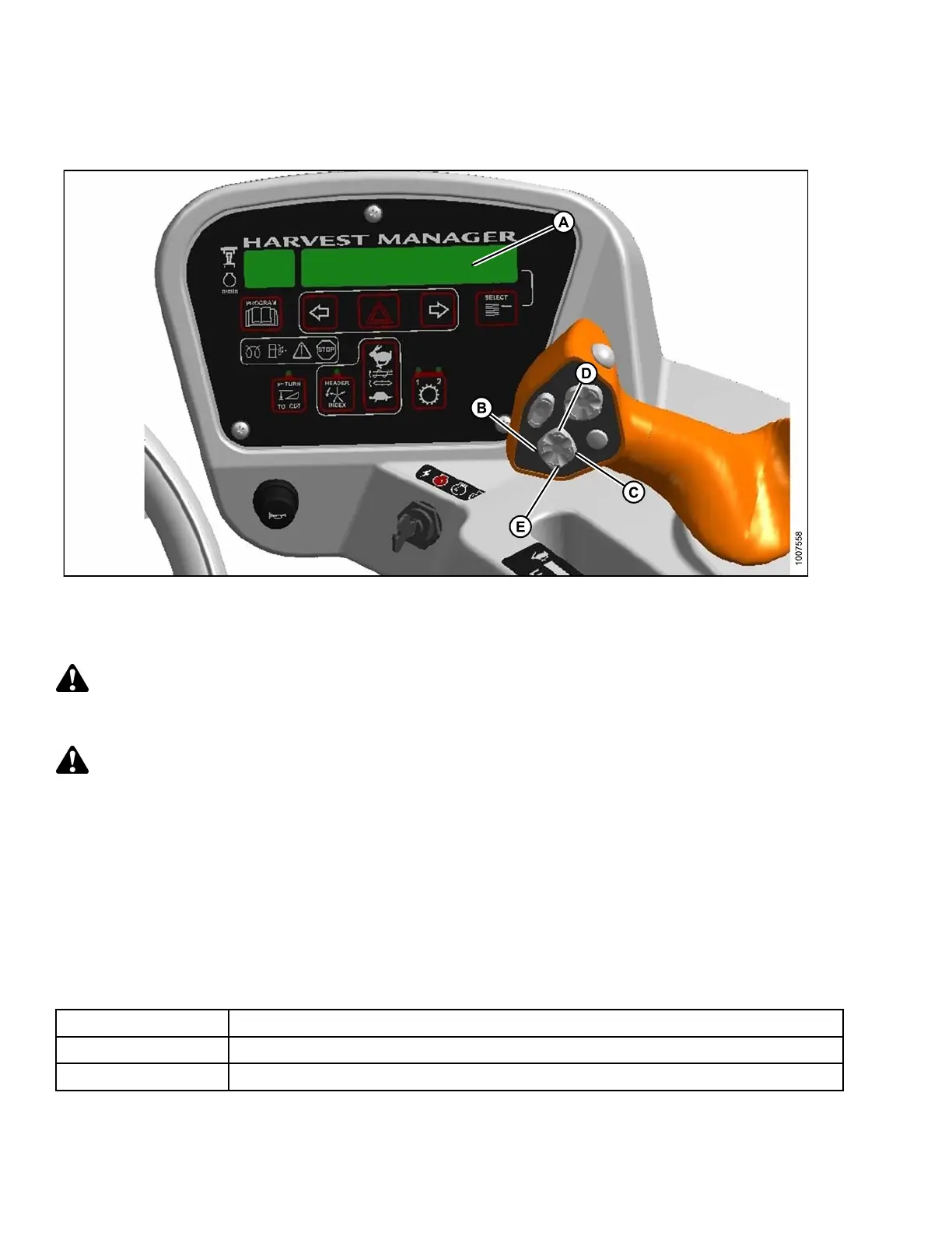
Figure 4.62: Cab Display Module (CDM) Float Adjustment
A-CDMDisplay
B-Heade
rTiltDown
C - Header Tilt Up
D-Heade
rUp
E - Heade
rDown
Check header float as follows:
DANGER
Stop engine and remove key from ignition before leaving operator's seat for any reason. A child or even a
pet could engage an idling machine.
CAUTION
Check to be sure all bystanders have cleared the area.
1. Start the engine.
2. If hydraulic center-link is installed, use HEADER TILT switches (B, C) to set center-link to mid-range position
(5.0 on CDM [A]).
3. Using HEADER DO W N switch (E), lower header fully w ith lift cylinders fully re tracted.
4. Shut down the engine and remove the key.
5. Grasp the divider rod at the end of the header and lift. The force to lift should be as noted in the following table
and should be approximately the same at both ends.
Header
Force Required to Lift Header at the Ends with Lift Cylinder Fully Retracted
Auger 75–85 lbf (335–380 N)
Draper
75–85 lbf (33 5– 3 80 N) with stabilizer/transport whe els raised (if equipped).
169890 120 Revision A