MAINTENANCE AND SERVICING
Header and Reel Hydraulics
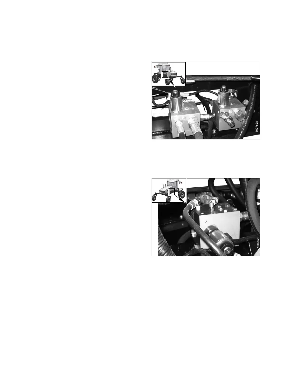
Flow Control Blocks
Two hyd ra ulic valve blocks with multiple cartridges are
used for the various windrower functions and are controlled
by the windrower control module (WCM) according to the
inputs from the Operator. The valve blocks are located
behind the left cab-forward side platform.
The valve blocks do NOT require any scheduled
maintenance other than to check for leaking fittings or
loose electrical connections. If service is required, contact
your MacDon Dealer.
Figure 5.185: Hydraulic Valve Blocks
Knife Drive Valv e Bloc k
The ON/OFF valve on the valve block turns the knife ON.
It is mounted on top of the knife drive pump.
The flow to the k nife drive is mechanically set on the pump
itself. Adjusting oil flow changes knife speed.
To set the knife speed, refer to the knife speed section for
your header type:
• D-Series header: 4.6.8 Knife Speed, page 175
• A-Series header: 4.7.3 Knife Speed, page 182
Knife speed varies depending on the header size, header
type, and whether the header has a single knife or double
knife.
Knife speed is NOT monitored by cab display module
(CDM) unless the optional expansion module MD #B4666
is installed. Refer to 7.1.10 Expansion Module, page 338.
Knife speed has been factory set for lower knife speeds.
Record the knife speed for your header type here:
• HEADER TYPE: ___________________________
• RECOMMENDED KNIFE SPEED: _____________
For units used with more than one header, knife speed will
need to be changed when switching headers.
Figure 5.186: Knife Drive Valve Block
169890 294 Revision A