MAINTENANCE AN D SERVICING
5.2.5 O-Ring B
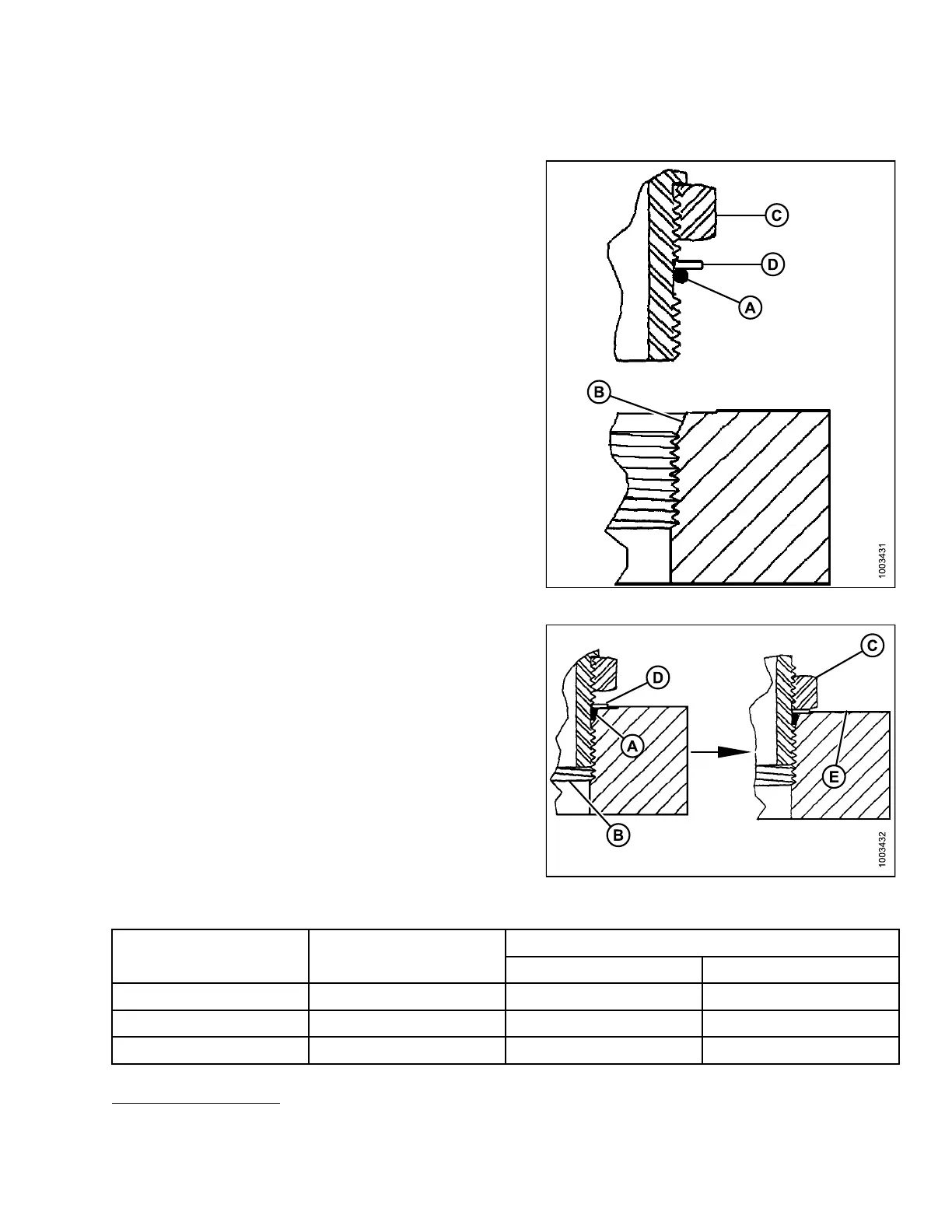
oss (ORB) Hydraulic Fittings (Adjustable)
1. Inspect O-ring (A) and seat (B) for dirt or
obvious defects.
2. Back off the lock nut (C) as far as possible. Ensure that
washer (D) is not loose and is pushed toward the lock
nut (C) as far as possible.
3. Check that O-ring (A) is NOT on the threads, adjust
if necessary.
4. Apply hydraulic system oil to the O-ring (A).
Figure 5
.11: Hydraulic Fitting
5. Install fi tting (B) into port until back up washer (D) and
O-ring (A) contacts on part face (E).
6. Position angle fittings by unscrewing no more than
one turn.
7. Turn lock nut (C) down to washer (D) and tighten to
torque shown. Use two wrenches, one on the fitting (B)
and the other on the lock nut (C).
8. Check the final condition of the fitting.
Figu
re 5.12: Hydraulic Fitting
Table 5.11 O-Ring Boss (ORB) Hydraulic Fittings (Adjustable)
Torque Value
20
SAE Dash Size Thread Size (in.)
ft·
lbf (*in·lbf) N·m
-3 3/8-24 *106–115 12–13
-4 7/16–20 14–15 19–21
-5 1/
2–20
15
–24
21
–33
20. Torque values shown are based on lubricated connections as in reassembly.
169890 193 Revision A