MAINTENANCE AN D SERVICING
5.2.6 O-Ring B
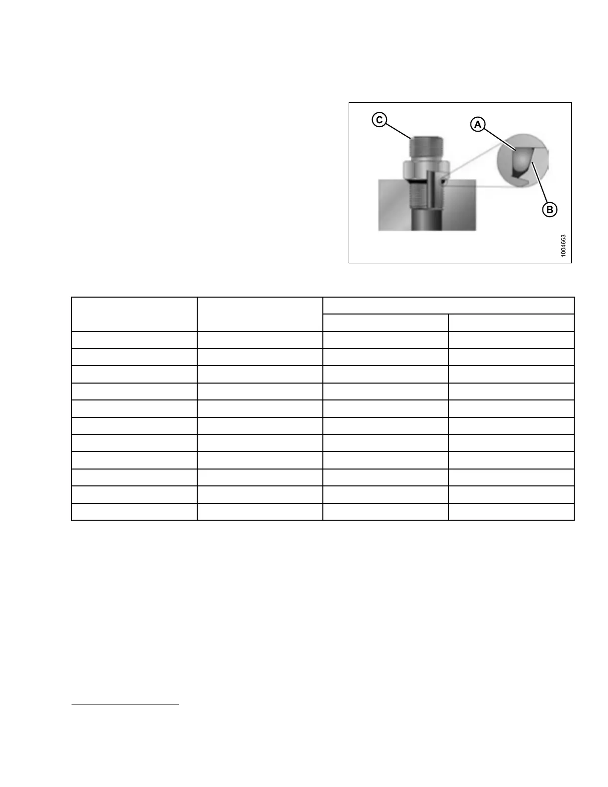
oss (ORB) Hydraulic Fittings (Non-Adjustable)
1. Inspect O-ring (A) and seat (B) for dirt or
obvious defects.
2. Check that O-ring (A) is NOT on the threads, adjust
if necessary.
3. Apply hydraulic system oil to the O-ring.
4. Install fi tting (C) into p o rt until fitting is hand tight.
5. Torque fitting (C) per value in chart. Refer to
Table 5.12 O-Ring Boss (ORB) Hydraulic Fittings
(Non-Adjustable), p age 195.
6. Check the final condition of the fitting.
Figure 5.13: Hydraulic Fitting
Table 5.12 O-Ring Boss (ORB) Hydraulic Fittings (Non-Adjustable)
Torque Value
21
SAE Dash Size Thread Size (in.)
ft·lbf (*in·lbf) N·m
-3 3/8-24 *106–11
5
12–13
-4 7/16–20 14–15 19–21
-5 1/2–20 15–24 21–33
-6 9/16–1
8
19–21 26–29
-8 3/4–16 34–37 46–50
-10 7/8–14 55–60 75–82
-12 1-1/
16-12
88–9
7
120–
132
-14 1-3/8-12 113–124 153–168
-16 1-5/16-12 130–142 176–193
-2
0
1-
5/8-12
16
3–179
22
1–243
-24 1-7/8-12 199–220 270–298
21. Torque values shown are based on lubricated connections as in reassembly.
169890 195 Revision A