OPERATION
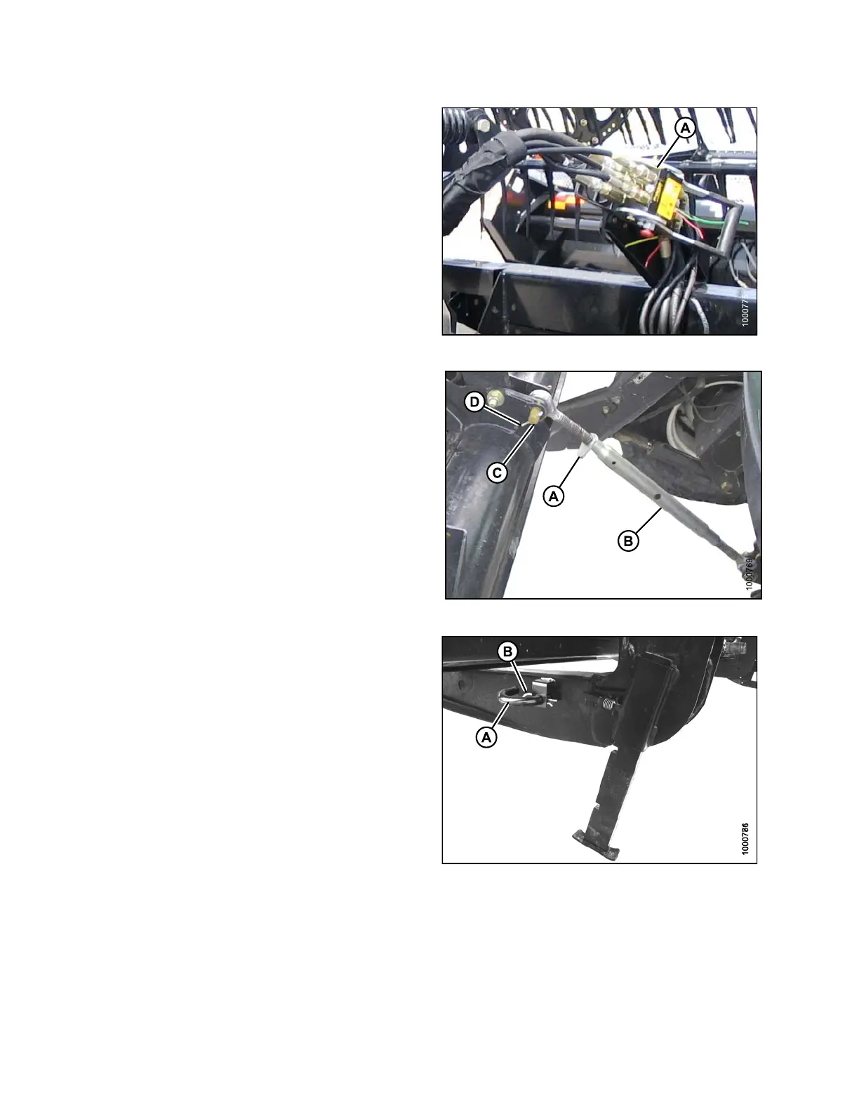
10. Disconnect reel hydraulics (A) from header and
store on bracket at windrower left cab-forward side.
Refer to the draper header operator ’s manual for
further information.
Figure 4.120: Reel Hydraulics
11. Loosen nut (A) and rotate barrel (B) to relieve load
on link.
12. Remove c otter pin on clevis pin (D) and remove the pin
(C) to disconnect from windrower. Rein stall clevis pin
(C) in header.
13. Tighten nut (A) against barrel. A slight tap with a
hammer is sufficient.
Figure 4
.121: Mechanical Center-Link
14. Reinstall pin (A) into header leg and secure with a
hairpin (B).
Figu
re 4.122: Header Leg
4.5.
3 Attaching an A-Series Header
Refer to the procedure that is appropriate for the center-link installed on the windrower:
• Attaching an A-Series Header: Hydraulic Center-Link, page 149
• Attaching an A-Series Header: Mechanical Center-Link, page 154
169890 148 Revision A