OPERATION
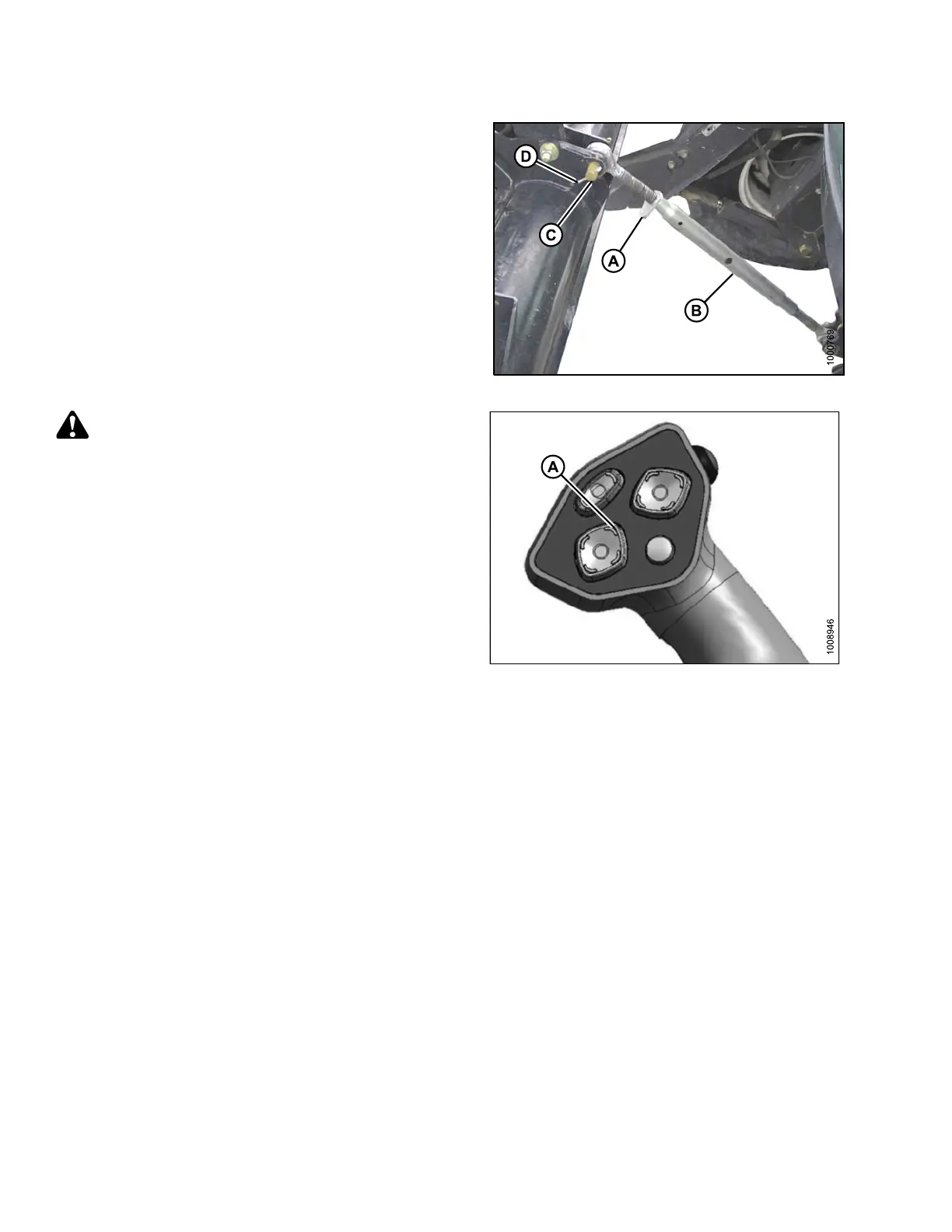
6. Loosen nut (A) and rotate barrel (B) to adjust length so
that the link lines-up with header bracket.
7. Install clevis pin (C) and secure with cotter pin (D).
8. Adjust link to required length for proper header angle
by rotating barrel (B). Tighten nut (A) against barrel. A
slight tap with a hammer is sufficient.
Figure 4.95
: Mechanical Center-Link
CAUTION
Check to be sur e all bystan d ers have cleared t he area.
9. Press the HEADER UP switch (A) to raise header to
maximum h eight.
NOTE:
If one end of the header does NOT raise fully, r ephase
the cylinders as follows:
a. Press and hold the HEADER UP switch until both
cylinders stop moving.
b. Continue to hold the switch for 3–4 seconds.
Cylinders are now phased.
Figure 4.96: GSL
169890 138 Revision A