230 POWER CYLINDERS
1
2
3
4
5
6
H06089
Figure 327 Cylinder sleeve clamping details
1. Fire dam (highest point on cylinder sleeve)
2. Clamping tool (washer)
3. Clamping bolt
4. Crankcase
5. Cylinder sleeve
6. Shim pack
1. Clean the cylinder sleeve, cylinder sleeve crevice
bore, and crankcase counterbore surface.
CAUTION: To prevent engine damage, do not
"torque-to- yield" the holding adapter bolts (as
when installing cylinder head bolts). This will
prevent stretching the bolts and risking the
indentation of tooling marks on the cylinder
sleeve.
2. Install the cylinder sleeve in the cylinder bore
without the crevice seal.
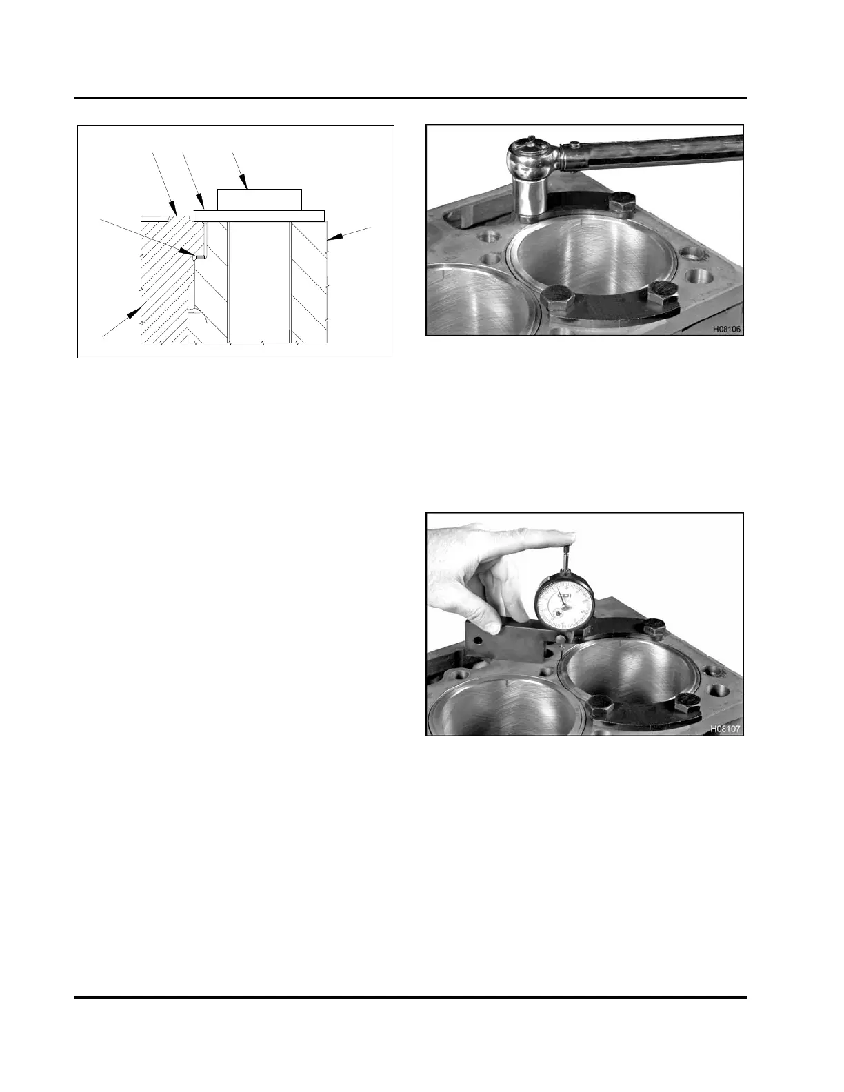
Figure 328 Installing the holding adapters
3. Install the cylinder sleeve holding adapters (Table
34) with 10.9 or higher grade bolts and hardened
washers. Tighten bolts in two stages:
A. 55 N·m (40 lbf·ft)
B. 110 N·m (80 lbf·ft)
Figure 329 Measuring cy
linder sleeve protrusion
4. Place the indicator ti
pofasurfacegaugeonthe
cylinder sleeve flan
ge. Zero the dial indicator.
5. Move the surface gaug
e until the indicator
tip slides off the fla
nge to the surface of the
crankcase. Record t
he cylinder sleeve protrusion
reading on the dial
indicator.
EGES-265-2
Read all safety instructions in the "Safety Information" section of this manual before doing any procedures.
Follow all warnings, cautions, and notes.
© 2009 Navistar, Inc.
 Loading...


