Installation of the converter
- 18 -
optek-converter C4101 Version 07.2009_1.2US, 23.07.2009
www.optek.com
6 Installation of the converter
Check the whole scope of supply for completeness. Check if there is any
detectable damage to the delivery. If you detect any damage or fault, contact our
customer service. See preliminary note for our contact data.
6.1 Installation site requirements for standard installation
• A control cabinet with a cutout for the converter as well as 4 drill holes
M2.5 for fixing must be provided.
Dimensioning details of the converter are given in the technical data.
• An external release device on the control cabinet must be close to the
converter. With this device the converter can be switched voltage-free.
Tool • Screw driver
6.2 Standard installation
1. Insert the converter into the cutout in the control cabinet.
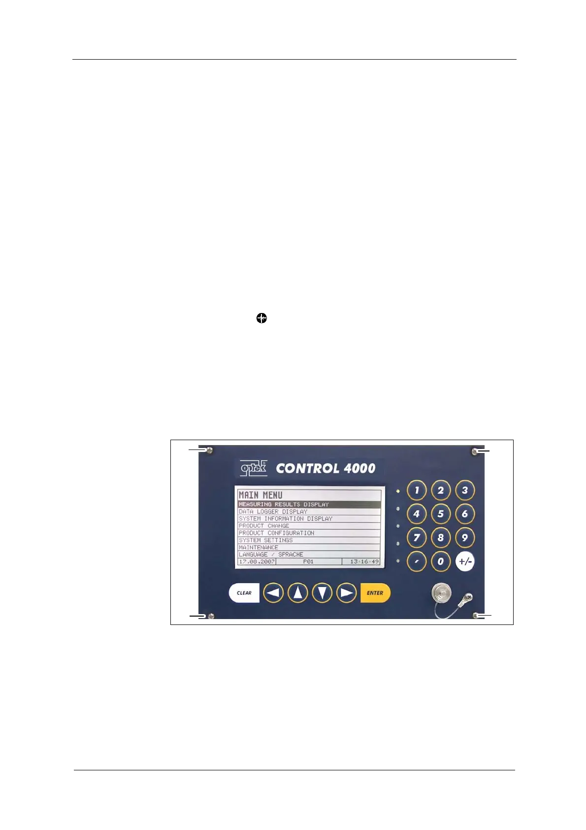
2. Fasten the four screws M2.5 x 11 (20, fig. 8) of the converter.
Fig. 8 Front view with screws