Software Version C
- 117 -
optek-converter C4101 Version 07.2009_1.2US, 23.07.2009
www.optek.com
9.10.11 Remote In
The converters C4121, C4221, C4222, C4322, and C4422 can be controlled via
the control system. 24 V DC control cables connected to the applicable remote
input clamps are used to activate different converter functions. (e.g. using PLC).
With this function, you can define how the remote inputs are to be implemented
on the converter. There are two possible settings: Remote In 1 or Remote In 2.
These settings allow a zeroing of the system, which is either global or specific to
measuring results.
• In Remote In 1 all inputs R1 to R7 are equal.
Product change and system zeroing can be carried out virtually
simultaneously. Here, zeroing is carried out globally, i.e. inputs A and D
are set to "0" simultaneously for all measuring results in all products.
• In Remote In 2 all inputs R1 to R4 are different. Here, zeroing is selective,
i.e. inputs A to D are only set to "0" when they are allocated to selected
measuring results of the current product.
If R6 = LOW, all other inputs are treated as in Remote In 1.
If R6 = HIGH, inputs R1 to R4 are used to selectively zero measuring
results M01 to M04.
Note!
Remote In 1 requires setting of the current product in R1 to R3, otherwise
zeroing with R6 results in a product change to P01!
Remote In 2 uses R1 to R4 for measuring result selection if R6 = HIGH
(see chapter 9.12.1, page 164)!
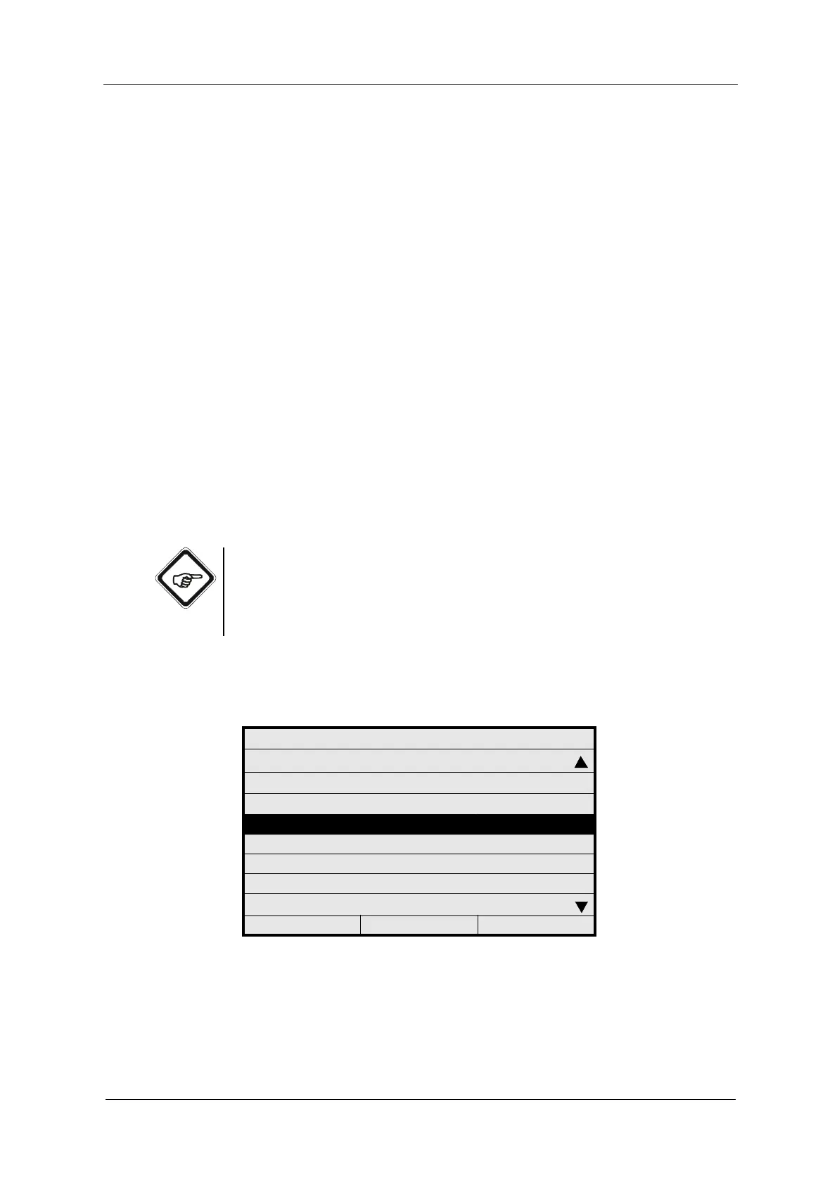
1. Select SYSTEM SETTINGS from the main menu and press [ENTER].
2. Select REMOTE IN and press [ENTER].
Fig. 121 Menu system settings, choosing Remote In
SYSTEM SETTINGS
SENSOR TF
mA OUTPUTS
RELAY OUTPUTS
REMOTE IN
HOLD
FAILSAFE
PASSWORD PROTECTION
OPTEK INPUTS
20:05:2006 P01 11:26:55