Wiring
- 30 -
optek-converter C4101 Version 07.2009_1.2US, 23.07.2009
www.optek.com
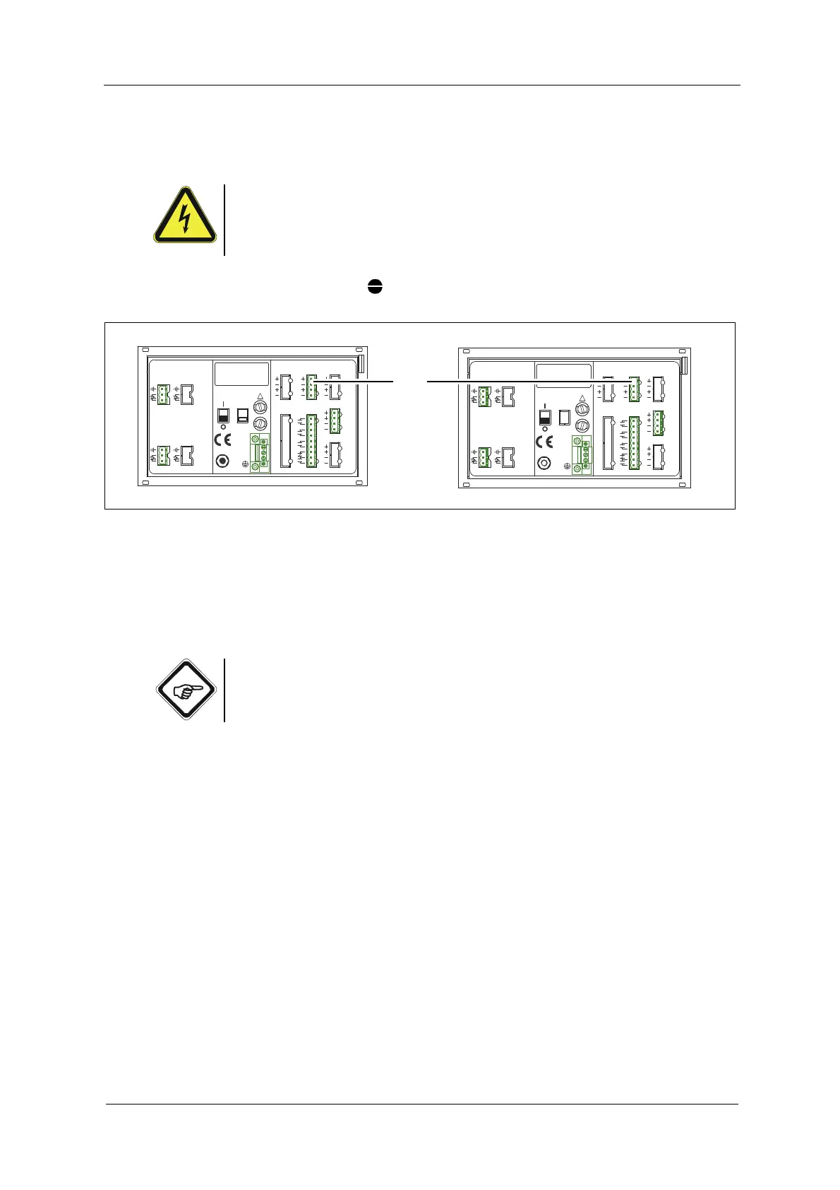
7.6 Connecting the mA-outputs
Danger!
Electrical voltage!
Switch the converter voltage-free before connecting!
Install electrical connections only by qualified electricians!
Tool • Screw driver
Fig. 20 mA-outputs
The converter is equipped with two independent mA-outputs (4, fig. 20), which
can be both switched between 0 - 20 mA and 4 - 20 mA in the software:
• mA-output 1 clamps 40 + / 41 -
• mA-output 2 clamps 42 + / 43 -
Note!
Observe the measuring results allocation on the corresponding mA-outputs
(M01 to mA-output 1, M02 to mA-output 2).
19 20 21
DETECTOR INPUTS
[C]
3
4
5
[D]
3
4
5
DETECTOR INPUTS
2
5
1
[A]
[B]
1
2
5
M6
PA
PE
L
N
24 V, T 3,15 A
24 V, DC / 50 / 60 Hz, 50 VA
!
24 V AC / DC24 V DC
OPTEK - DANULAT
R5
R8
RR
R6
R7
R3
R4
R2
R1
35
38
39
36
37
33
34
32
31
MADE IN GERMANY
14
17
18
15
16
12
13
11
10
LAMP [F]
RELAY OUT
4 - 20 mA
REMOTE IN
IN 1, 2
24
23
21
22
0 / 4 - 20 mA
43
42
40
41
OUT 1, 2
LAMP [E]
OUT 3, 4
cable
length
V DC
acc. to
7
7
6
6
cable
length
V DC
acc. to
7
7
6
6
47
46
44
45
212019
DETECTOR INPUTS
[C]
5
4
3
[D]
5
4
3
DETECTOR INPUTS
[A]
1
2
5
[B]
1
2
5
OPTEK - DANULAT
REMOTE IN
4 - 20 mA
PA
M6
N
PE
L
230V
R5
R6
R7
RR
R8
24 V DC
R1
R3
R4
R2
115 / 230 V, 50 / 60 Hz, 50 VA
115 / 230 V, T 1,6 A
!
IN 1, 2
MADE IN GERMANY
24 V AC / DC
35
36
37
39
38
31
33
34
32
14
15
16
18
17
10
12
13
11
6
6
7
7
LAMP [F]
6
6
7
7
acc. to
cable
length
V DC
acc. to
V DC
length
cable
0 / 4 - 20 mA
OUT 1, 2
RELAY OUT
21
22
24
23
40
41
43
42
44
45
47
46
LAMP [E]
OUT 3, 4