Wiring
- 23 -
optek-converter C4101 Version 07.2009_1.2US, 23.07.2009
www.optek.com
7.4 Connecting the sensors
Danger!
Electrical voltage!
Switch the converter voltage-free before connecting the sensor!
Install electrical connections only by qualified electricians!
Connection to the
converter
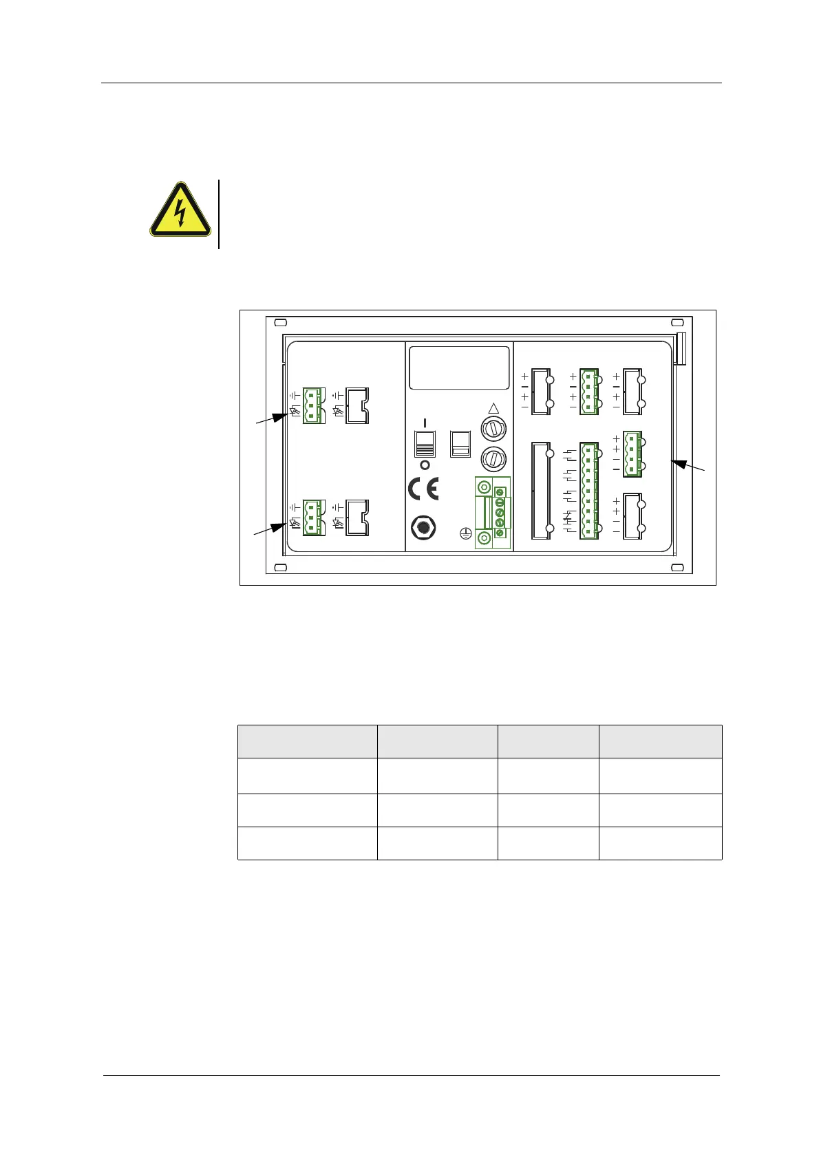
The following connections are on the back of the converter:
Fig. 15 Detector inputs and lamp outputs
Letters stand for
• A, C detector inputs (C is inactive at C4101)
• E connection for lamp output
Tab. 5 Connections
Number of sensors
sensor type
Detector input Lamp output
Cable set standard
length up to
1 sensor
AF16 A E
100 m / 328 ft.
*
*. Cable sets length > 100 m (328 ft.) on request.
1 sensor
AS16 / AS16-BT
AE
50 m / 164 ft.
1 sensor
AS56
AE
50 m / 164 ft.
212019
DETECTOR INPUTS
[C]
5
4
3
[D]
5
4
3
DETECTOR INPUTS
[A]
1
2
5
[B]
1
2
5
OPTEK - DANULAT
REMOTE IN
4 - 20 mA
PA
M6
N
PE
L
230V
R5
R6
R7
RR
R8
24 V DC
R1
R3
R4
R2
115 / 230 V, 50 / 60 Hz, 50 VA
115 / 230 V, T 1,6 A
!
IN 1, 2
MADE IN GERMANY
24 V AC / DC
35
36
37
39
38
31
33
34
32
14
15
16
18
17
10
12
13
11
6
6
7
7
LAMP [F]
6
6
7
7
acc. to
cable
length
V DC
acc. to
V DC
length
cable
0 / 4 - 20 mA
OUT 1, 2
RELAY OUT
21
22
24
23
40
41
43
42
44
45
47
46
LAMP [E]
OUT 3, 4
A
C
E