Software Version C
- 76 -
optek-converter C4101 Version 07.2009_1.2US, 23.07.2009
www.optek.com
9.5.6 Define limit values
With this function, three limit values can be defined separately for each product.
When a value falls below these set limit values or exceeds it, an alarm is
triggered. The limit values are always displayed in the MEASUREMENT
DISPLAY and the yellow LEDs on the front panel of the converter indicate the
alarm!
The limit values (G01 to G03) are assigned to the following relay outputs (REL):
• G01 => REL 01 - clamps 10 / 11
• G02 => REL 02 - clamps 12 / 13
• G03 => REL 03 - clamps 14 / 15
Note!
To function as limit value alarm devices, the relay outputs must be defined as
limit values in the SYSTEM SETTINGS menu. Proceed according to the
instructions in chapter 9.10.10, page 115.
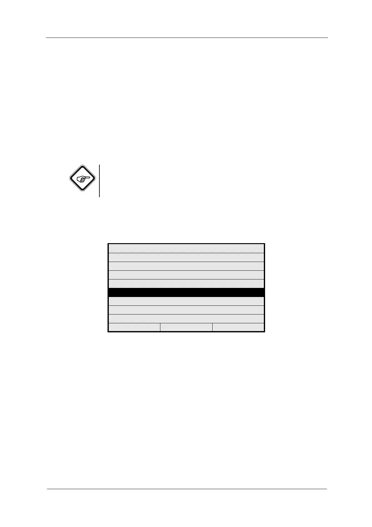
To define limit values, proceed as follows:
1. Select the DEFINE LIMIT VALUES function in the PRODUCT menu and
press [ENTER].
Fig. 69 Choosing define limit values
PRODUCT: P01
DEFINE PRODUCT NAME
DEFINE MEASURING RESULT
DEFINE LINEARIZATION
DEFINE OFFSET + SLOPE SET
DEFINE LIMIT VALUES
DEFINE DISPLAY
DISPLAY FORMULA
DISPLAY L21 - L28
20:05:2006 P01 11:26:55