9.22
SEL-351A Relay Instruction Manual Date Code 20080213
Setting the Relay
Relay Word Bits (Used in SEL
OGIC Control Equations)
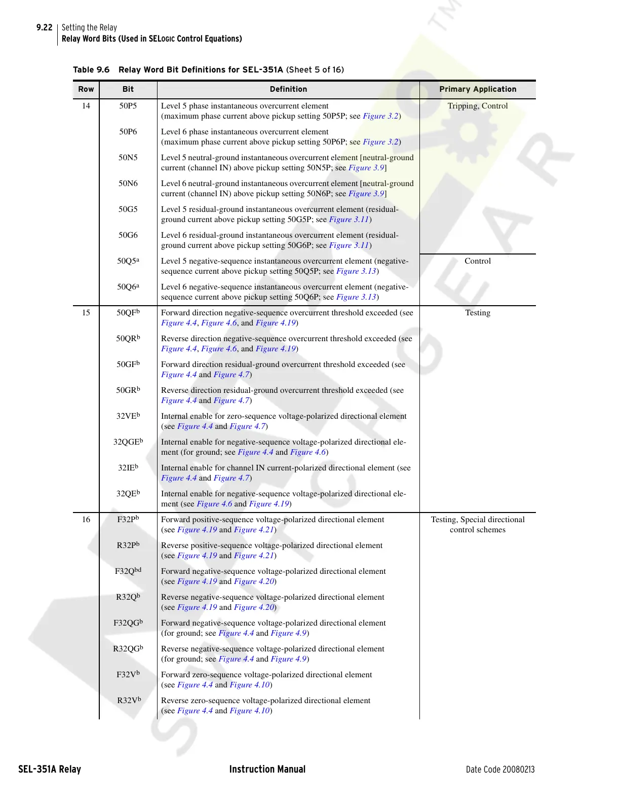
14 50P5 Level 5 phase instantaneous overcurrent element
(maximum phase current above pickup setting 50P5P; see Figure 3.2)
Tripping, Control
50P6 Level 6 phase instantaneous overcurrent element
(maximum phase current above pickup setting 50P6P; see Figure 3.2)
50N5 Level 5 neutral-ground instantaneous overcurrent element [neutral-ground
current (channel IN) above pickup setting 50N5P; see Figure 3.9]
50N6 Level 6 neutral-ground instantaneous overcurrent element [neutral-ground
current (channel IN) above pickup setting 50N6P; see Figure 3.9]
50G5 Level 5 residual-ground instantaneous overcurrent element (residual-
ground current above pickup setting 50G5P; see Figure 3.11)
50G6 Level 6 residual-ground instantaneous overcurrent element (residual-
ground current above pickup setting 50G6P; see Figure 3.11)
50Q5
a
Level 5 negative-sequence instantaneous overcurrent element (negative-
sequence current above pickup setting 50Q5P; see Figure 3.13)
Control
50Q6
a
Level 6 negative-sequence instantaneous overcurrent element (negative-
sequence current above pickup setting 50Q6P; see Figure 3.13)
15 50QF
b
Forward direction negative-sequence overcurrent threshold exceeded (see
Figure 4.4, Figure 4.6, and Figure 4.19)
Testing
50QR
b
Reverse direction negative-sequence overcurrent threshold exceeded (see
Figure 4.4, Figure 4.6, and Figure 4.19)
50GF
b
Forward direction residual-ground overcurrent threshold exceeded (see
Figure 4.4 and Figure 4.7)
50GR
b
Reverse direction residual-ground overcurrent threshold exceeded (see
Figure 4.4 and Figure 4.7)
32VE
b
Internal enable for zero-sequence voltage-polarized directional element
(see Figure 4.4 and Figure 4.7)
32QGE
b
Internal enable for negative-sequence voltage-polarized directional ele-
ment (for ground; see Figure 4.4 and Figure 4.6)
32IE
b
Internal enable for channel IN current-polarized directional element (see
Figure 4.4 and Figure 4.7)
32QE
b
Internal enable for negative-sequence voltage-polarized directional ele-
ment (see Figure 4.6 and Figure 4.19)
16 F32P
b
Forward positive-sequence voltage-polarized directional element
(see Figure 4.19 and Figure 4.21)
Testing, Special directional
control schemes
R32P
b
Reverse positive-sequence voltage-polarized directional element
(see Figure 4.19 and Figure 4.21)
F32Q
bd
Forward negative-sequence voltage-polarized directional element
(see Figure 4.19 and Figure 4.20)
R32Q
b
Reverse negative-sequence voltage-polarized directional element
(see Figure 4.19 and Figure 4.20)
F32QG
b
Forward negative-sequence voltage-polarized directional element
(for ground; see Figure 4.4 and Figure 4.9)
R32QG
b
Reverse negative-sequence voltage-polarized directional element
(for ground; see Figure 4.4 and Figure 4.9)
F32V
b
Forward zero-sequence voltage-polarized directional element
(see Figure 4.4 and Figure 4.10)
R32V
b
Reverse zero-sequence voltage-polarized directional element
(see Figure 4.4 and Figure 4.10)
Table 9.6 Relay Word Bit Definitions for SEL-351A (Sheet 5 of 16)
Row Bit Definition Primary Application
Courtesy of NationalSwitchgear.com