9.23
Date Code 20080213 Instruction Manual SEL-351A Relay
Setting the Relay
Relay Word Bits (Used in SEL
OGIC Control Equations)
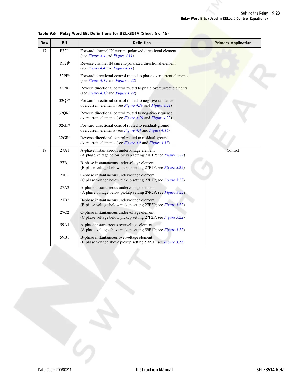
17 F32I
b
Forward channel IN current-polarized directional element
(see Figure 4.4 and Figure 4.11)
R32I
b
Reverse channel IN current-polarized directional element
(see Figure 4.4 and Figure 4.11)
32PF
b
Forward directional control routed to phase overcurrent elements
(see Figure 4.19 and Figure 4.22)
32PR
b
Reverse directional control routed to phase overcurrent elements
(see Figure 4.19 and Figure 4.22)
32QF
b
Forward directional control routed to negative-sequence
overcurrent elements (see Figure 4.19 and Figure 4.22)
32QR
b
Reverse directional control routed to negative-sequence
overcurrent elements (see Figure 4.19 and Figure 4.22)
32GF
b
Forward directional control routed to residual-ground
overcurrent elements (see Figure 4.4 and Figure 4.15)
32GR
b
Reverse directional control routed to residual-ground
overcurrent elements (see Figure 4.4 and Figure 4.15)
18 27A1 A-phase instantaneous undervoltage element
(A phase voltage below pickup setting 27P1P; see Figure 3.22)
Control
27B1 B-phase instantaneous undervoltage element
(B phase voltage below pickup setting 27P1P; see Figure 3.22)
27C1 C-phase instantaneous undervoltage element
(C phase voltage below pickup setting 27P1P; see Figure 3.22)
27A2 A-phase instantaneous undervoltage element
(A phase voltage below pickup setting 27P2P; see Figure 3.22)
27B2 B-phase instantaneous undervoltage element
(B phase voltage below pickup setting 27P2P; see Figure 3.22)
27C2 C-phase instantaneous undervoltage element
(C phase voltage below pickup setting 27P2P; see Figure 3.22)
59A1 A-phase instantaneous overvoltage element
(A phase voltage above pickup setting 59P1P; see Figure 3.22)
59B1 B-phase instantaneous overvoltage element
(B phase voltage above pickup setting 59P1P; see Figure 3.22)
Table 9.6 Relay Word Bit Definitions for SEL-351A (Sheet 6 of 16)
Row Bit Definition Primary Application
Courtesy of NationalSwitchgear.com