A.3
Date Code 20080213 Instruction Manual SEL-351A Relay
Firmware and Manual Versions
Firmware
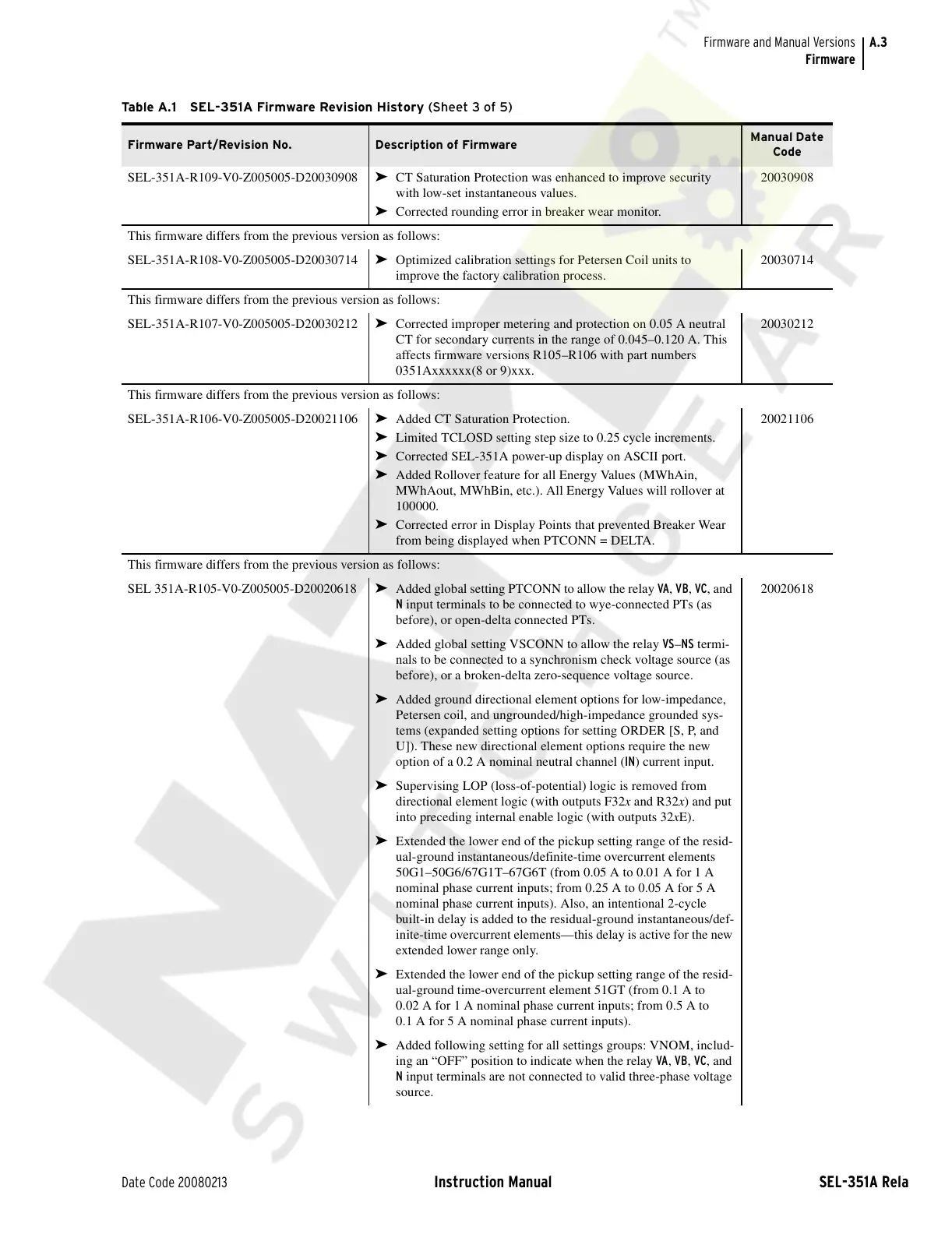
SEL-351A-R109-V0-Z005005-D20030908 ➤ CT Saturation Protection was enhanced to improve security
with low-set instantaneous values.
➤ Corrected rounding error in breaker wear monitor.
20030908
This firmware differs from the previous version as follows:
SEL-351A-R108-V0-Z005005-D20030714 ➤ Optimized calibration settings for Petersen Coil units to
improve the factory calibration process.
20030714
This firmware differs from the previous version as follows:
SEL-351A-R107-V0-Z005005-D20030212
➤ Corrected improper metering and protection on 0.05 A neutral
CT for secondary currents in the range of 0.045–0.120 A. This
affects firmware versions R105–R106 with part numbers
0351Axxxxxx(8 or 9)xxx.
20030212
This firmware differs from the previous version as follows:
SEL-351A-R106-V0-Z005005-D20021106
➤ Added CT Saturation Protection.
➤ Limited TCLOSD setting step size to 0.25 cycle increments.
➤ Corrected SEL-351A power-up display on ASCII port.
➤ Added Rollover feature for all Energy Values (MWhAin,
MWhAout, MWhBin, etc.). All Energy Values will rollover at
100000.
➤ Corrected error in Display Points that prevented Breaker Wear
from being displayed when PTCONN = DELTA.
20021106
This firmware differs from the previous version as follows:
SEL 351A-R105-V0-Z005005-D20020618
➤ Added global setting PTCONN to allow the relay VA, VB, VC, and
N input terminals to be connected to wye-connected PTs (as
before), or open-delta connected PTs.
20020618
➤ Added global setting VSCONN to allow the relay VS–NS termi-
nals to be connected to a synchronism check voltage source (as
before), or a broken-delta zero-sequence voltage source.
➤ Added ground directional element options for low-impedance,
Petersen coil, and ungrounded/high-impedance grounded sys-
tems (expanded setting options for setting ORDER [S, P, and
U]). These new directional element options require the new
option of a 0.2 A nominal neutral channel (IN) current input.
➤ Supervising LOP (loss-of-potential) logic is removed from
directional element logic (with outputs F32x and R32x) and put
into preceding internal enable logic (with outputs 32xE).
➤ Extended the lower end of the pickup setting range of the resid-
ual-ground instantaneous/definite-time overcurrent elements
50G1–50G6/67G1T–67G6T (from 0.05 A to 0.01 A for 1 A
nominal phase current inputs; from 0.25 A to 0.05 A for 5 A
nominal phase current inputs). Also, an intentional 2-cycle
built-in delay is added to the residual-ground instantaneous/def-
inite-time overcurrent elements—this delay is active for the new
extended lower range only.
➤ Extended the lower end of the pickup setting range of the resid-
ual-ground time-overcurrent element 51GT (from 0.1 A to
0.02 A for 1 A nominal phase current inputs; from 0.5 A to
0.1 A for 5 A nominal phase current inputs).
➤ Added following setting for all settings groups: VNOM, includ-
ing an “OFF” position to indicate when the relay VA, VB, VC, and
N input terminals are not connected to valid three-phase voltage
source.
Table A.1 SEL-351A Firmware Revision History (Sheet 3 of 5)
Firmware Part/Revision No. Description of Firmware
Manual Date
Code
Courtesy of NationalSwitchgear.com


 To Next Page