Section 06 ENGINE MANAGEMENT (RFI)
Subsection 03 (COMPONENT ADJUSTMENT, INSPECTION AND REPLACEMENT)
NOTE: Troubleshooting should be performed us-
ing the VCK. After a problem has been solved, en-
sure to clear the fault(s). Refer to DIAGNOSTIC
PROCEDURES.
It is possible that a component seems to operate
in static condition but in fact, it is defective. In
this case, the best way to solve this problem is
to remove the original part and replace it with one
which is in good condition.
Never use a battery charger to replace temporari-
ly the battery, as it may cause the ECM or VCM
to work erratically or not to work at all. Check
related-circuit fuse solidity and condition with an
ohmmeter. Visual inspection could lead to false
results.
WARNING
Some components are permanently con-
nected to the battery positive terminal, even
when the safety lanyard is removed. Always
disconnect the battery prior to disconnecting
any electric or electronic parts.
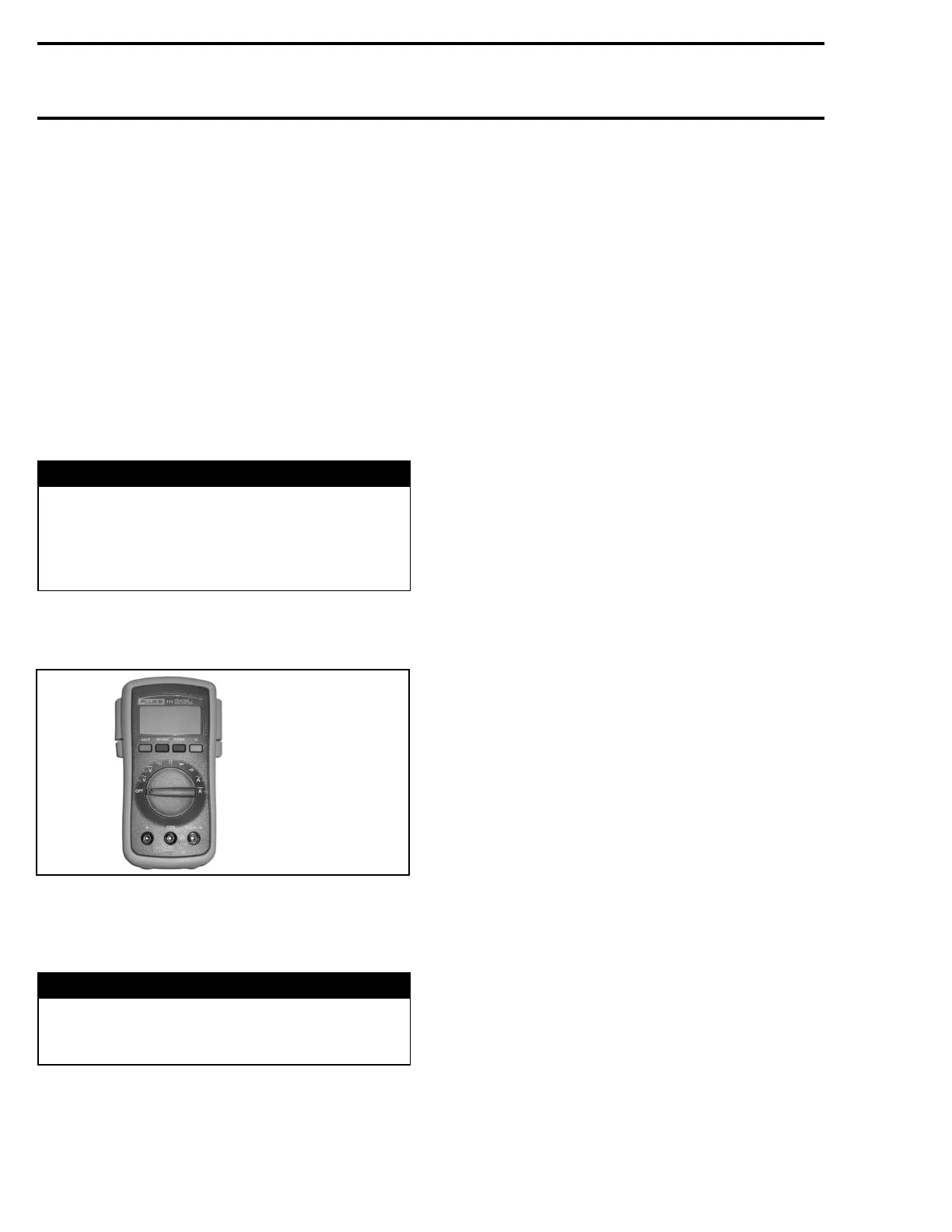
To perform verifications, a good quality multimeter
such as Fluke 111 (P/N 529 035 868) should be
used.
529 035 868
Pay particular attention to ensure that pins are
not out of their connectors or out of shape. The
troubleshooting procedures cover problems not
resulting from one of these causes.
WARNING
Ensure all terminals are properly crimped on
wires and connector housings are properly
fastened.
Before replacing a ECM, always check electri-
cal connections. Make sure that they are very
tight and they make good contact and that they
are corrosion- free. A “defective module” could
possibly be repaired simply by unplugging and
replugging the ECM. The voltage and current
might be too weak to go through dirty wire pins.
Check carefully if posts show signs of moisture,
corrosion or if they look dull. Clean pins properly
and then coat them with silicon-based dielectric
grease or other appropriate lubricant (except if
otherwise specified) when reassembling them.
If the newly replaced ECM is working, try the old
one and recheck if it works.
Ignition Components
NOTE: Ensure that all electronic components
are genuine – particularly in the ignition system.
Installing resistive caps, non-resistive spark plug
cables (or modified length) or non-resistive spark
plugs may lead to generate fault codes or bad
operation.
Resistance Measurement
Whenmeasuringtheresistancewithanohmme-
ter, all values are given for a temperature of 20°C
(68°F). The resistance value of a resistance varies
with the temperature. The resistance value for
usual resistor or windings (such as injectors) in-
creases as the temperature increases. However,
our temperature sensors are NTC types (Negative
Temperature Coefficient) and work the opposite
which means that the resistance value decreases
as the temperature increases. Take it into account
when measuring at temperatures different from
20°C(68°F). Use this table for resistance variation
relative to temperature for temperature sensors.
126 smr2005-056