Section 06 ENGINE MANAGEMENT (RFI)
Subsection 03 (COMPONENT ADJUSTMENT, INSPECTION AND REPLACEMENT)
Electrical Test
Voltage Test
Safety lanyard must be on DESS post.
Using the vehicle communication kit (VCK) with
the B.U.D.S. software, energize the fuel injector
from the Activation tab.
You should hear the injector working.
If the injector does not work, disconnect the con-
nector from the injector.
Install a temporary connector on the injector with
wireslongenoughtomaketheconnectionout-
side the bilge and apply voltage (12 V) to this test
harness.
CAUTION: While doing fuel injector electrical
test, do not apply continuous voltage to the
connector for more than 10 seconds. This can
damage the injector.
This will validate the injector mechanical and elec-
trical operation.
If it does not work, replace it. If it works, continue
procedure.
Using B.U.D.S., activate injector while probing ter-
minal as shown.
INJECTOR CONNECTOR MEASUREMENT
Pin 1 and battery ground
Pulsating voltage
approx 9 Vdc
BAT
Vdc
1
smr2005-056-011_a
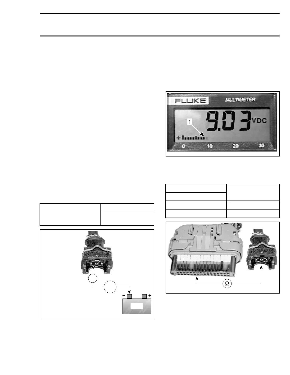
NOTE: Because B.U.D.S. sends pulsating voltage
to the injector, you will not read full 12 V. Short
readings of approximately 9 V indicate a working
injector. Since the analog display of the multime-
ter is faster than the numeric display, watching the
analog scale movement is better to see voltage
bursts.
smr2005-056-010_a
1. Analog scale
– If proper voltage is read, check continuity of
ground and power circuits as follows.
VCM CONNECTOR
PIN
INJECTOR
5-32
1(MAG),pin2
5-16
2(PTO),pin2
smr2005-056-012_a
smr2005-056 133