Service Manual
4-175
Installation
Connections to the system’s MDF
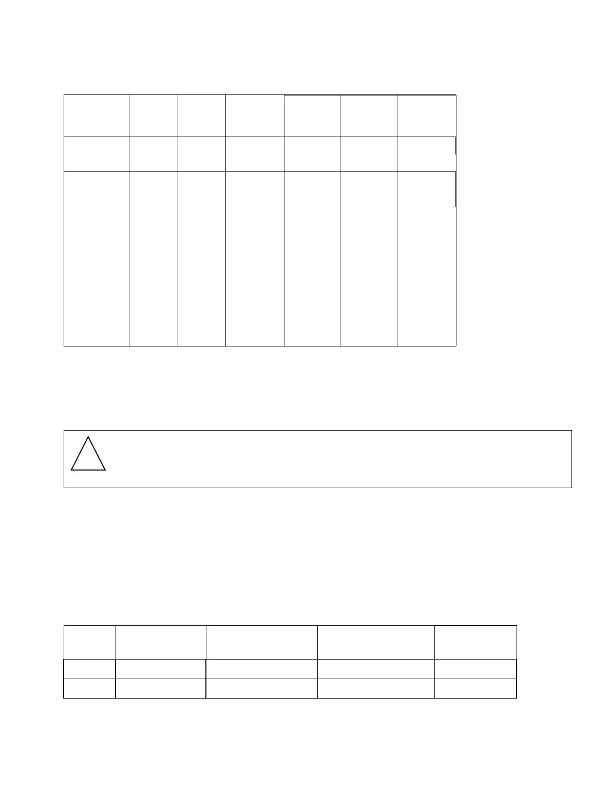
Table 4-5 Example of extension locations on the HiPath 1150 Main Distribution Frame
4.9.3 HiPath 1190/1190R
Example
Due to the flexibility of the HiPath 1190 systems, the configuration of expansion and optional
modules can vary according to each client’s needs. Here is an example of a possible
configuration:
For a system with a TME1 module in slot 1 and an EB 012 module in slot 3. The Main
Distribution Frame would be configured as follows:
Table 4-6 Example of extension locations on the Main Distribution Frame
Slot
External
Line #
Exten-
sion slot
Internal #
EB 210
module
Internal #
EB 206
module
EB 202
module
Internal #
Internal #
EB 200
module
Position 4
09 809 809 809 809
10 810 810 810 810
A/B
41 51 39 27
42 52 40 28
43 53 41
44 54 42
45 55 43
46 56 44
47 57
48 58
49 59
50 60
Warning
On the HiPath 1190, trunks and extensions lines must be routed to use the shortest
path inside the cabinet.
Module Slot
External digital
line #
Analog extension
position
Internal #
TME1 Position 1 01 to 30 --- 801 to 830
EB 012 Position 3 --- 1 to 12 101 to 112
!
 Loading...