Service Manual
4-187
Installation
Installing telephone terminals
Connections
Figure 4-46 Connections for telephone jacks (for Brazil)
Red wire (R) = voice (extension’s B wire).
Green wire (G) = voice (extension’s A wire).
Black wire (BK) =CD card’s C wire (positive in relation to D).
Yellow wire (Y) =CD card’s D wire (negative in relation to C).
Installation Procedures
Step Procedure
1. Install telephone jacks at the extensions.
2. Connect each extension jack to the desired A/B slot on the Main Distribution Frame.
3. KS-type system telephones are preset at factory default for C/D pairs. (see “CD
Interface Assignment” on page 6-248).
If necessary, choose a different C/D pair, then program the new C/D interface
assignment.
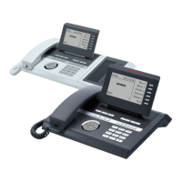
4. Install the telephone sets.
5. “Performing a visual inspection” on page 4-189.
6. Configure the required data (see “Operation” on page 7-278).

 Loading...


