3. Select "Next step >".
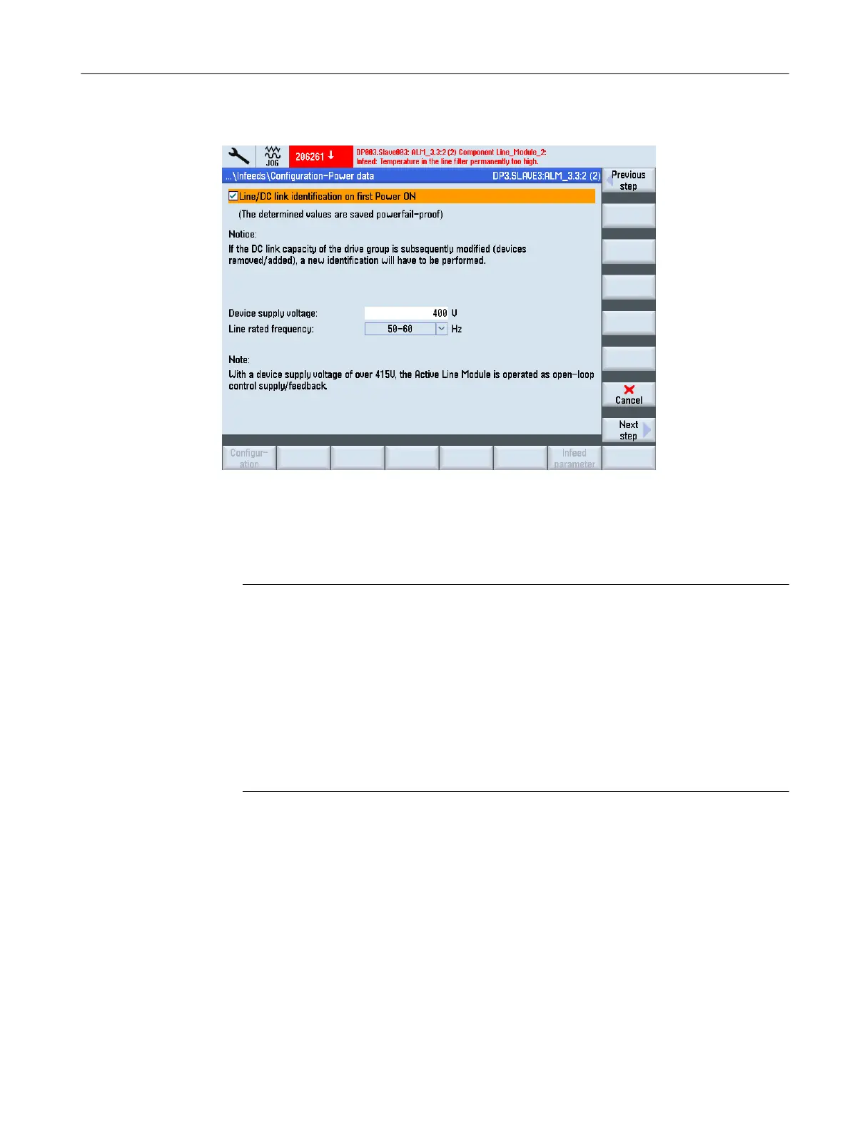
Figure 5-6 Infeeds > Line data
The following supply system data is configured:
– When selecting the checkbox,
the line/intermediate circuit identification is activated once
the pulse is enabled of the infeed (p3410). The infeed then switches to operational mode.
Note
DC link identification
If the line supply environment changes or the components on the intermediate circuit
change
(e.g.
after
setting
up the equipment at the customer site or after expanding the
drive group), the checkbox must be set again: Hence the "Supply system data" softkey
in the overview in order to restart the supply system / DC link circuit identification.
If p3410 = 5 is saved in the commissioning archive, then the supply system / DC link
identification starts automatically once the drive data is input into the archive.
Only then can it be guaranteed that the infeed operates with the optimum controller
settings.
– Enter the device supply voltage: This is the basis for monitoring the supply voltage
(p0281
-
p0283),
whereby
an alarm is triggered in the case of an overshoot or undershoot
(alarm threshold and shutdown threshold). The actual supply voltage is determined
automatically and the adjustment is made based on this value.
– The actual line frequency for the infeed is determined automatically.
– In parameter p0284, p0285, set a threshold above which an alarm is triggered (default
setting of the monitoring: 45 Hz to 65 Hz).
Commissioning the drive
5.1 Commissioning the drive
CNC commissioning
Commissioning Manual, 10/2015, 6FC5397-3DP40-5BA3 121

 Loading...


