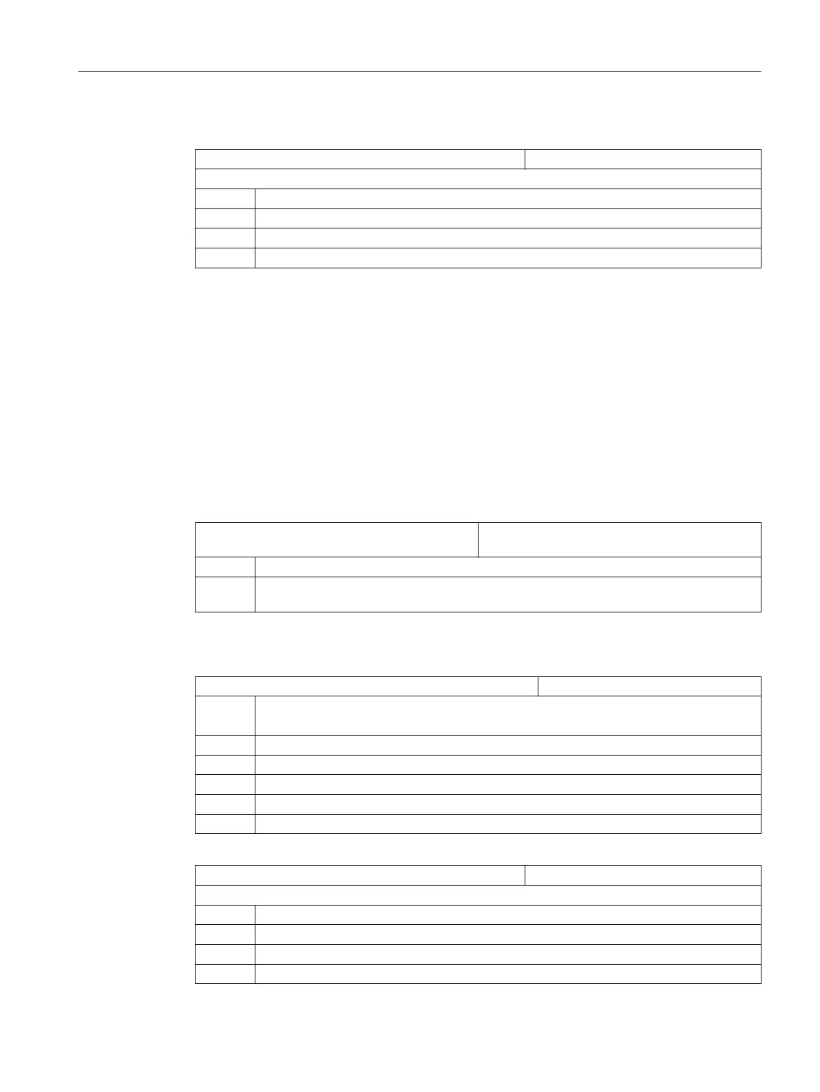
For plane selection when milling, appropriately set the following machine data:
MD52005 $MCS_DISP_PLANE_MILL Plane selection for milling
= 17
= 0 In the cycle support
= 17 G17 (default value)
= 18 G18
= 19 G19
Simulation and simultaneous recording
In order that simulation and simultaneous recording are displayed without any errors, set the
machine data as described in the following section:
Setting the technology for simulation
(Page 67)
Defining the direction of rotation
In order that the direction of rotation is correctly displayed in the ShopMill user interface, and
when
programming
ShopMill
functions, the correct direction of rotation is executed, you must
make some settings that are coordinated with one another. You must align these settings to
the actual direction of rotation of the axis at the machine.
MD52207 $MCS_USAGE_ATTRIB[n] Attribute of the axes in the channel
[n] channel axis number
Bit 4 Displayed direction of rotation for M3 is counter-clockwise (for spindles)
Bit 5 Direction of rotation M3 corresponds to rotary axis minus (for spindles)
This bit must be set analog to PLC bit DB38xx.DBX2001.6.
Additional channel-specific machine data
MD52216 $MCS_FUNCTION_MASK_DRILL Drilling function screen form
Bit 2 Tapping also without encoder
The
setting depends on
whether at the machine the tool spindle is equipped with an encoder.
= 0 Tapping only possible with encoder
= 1 Tapping also possible without encoder
Bit 3 Constant cutting speed referred to the diameter of the centering
= 0 Constant cutting speed referred to the diameter of the tool
= 1 Constant cutting speed referred to the diameter of the centering
MD52229 $MCS_ENABLE_QUICK_M_CODES Enable fast M commands
= 0
Bit 0 Coolant OFF (default value)
Bit 1 Coolant 1 ON
Bit 2 Coolant 2 ON
Bit 3 Coolants 1 and 2 ON
Configuring cycles
7.4 Milling
SINUMERIK Operate
Commissioning Manual, 10/2015, 6FC5397-3DP40-5BA3 97

 Loading...


