5HIHUHQFHSRLQWRI
WKHPDFKLQH
0.6;<=
5RWDU\D[LV$
5RWDU\D[LV&
O
O[
O
O
]
O O
9
O ,,
=
<
;
9
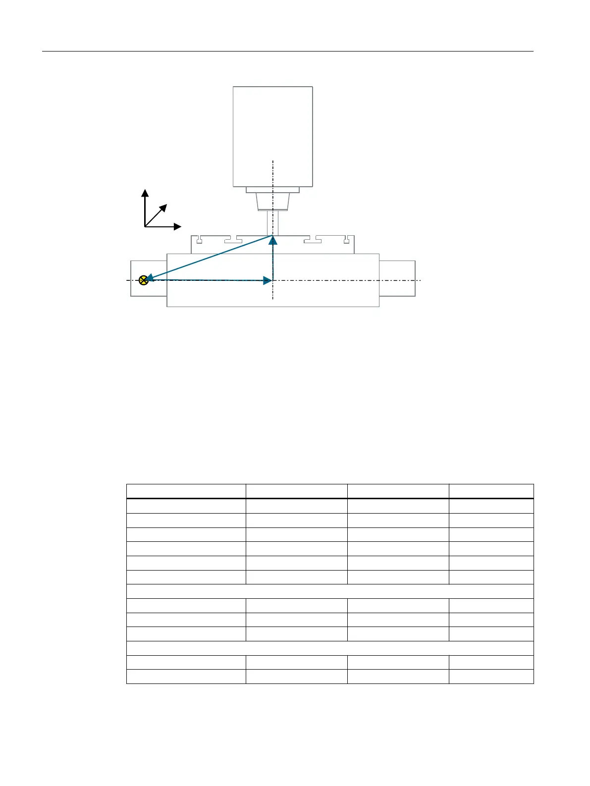
Rotary axis vector V1 The rotary axis A rotates about X.
Rotary axis vector V2 Rotary axis C rotates about Z.
Offset vector I2 The distance from the reference point of the machine to the center of rotation/
intersection of rotary axis 1.
Offset vector I3 The distance from the center of rotation of rotary axis 1 to the center of rota‐
tion/intersection of rotary axis 2.
Offset vector I4 Closure of vector chain, I4 = - (I2 + I3).
Figure 7-14 Front view of the machine from the Y direction
Kinematics Swivel table TABLE_5
X Y Z
Offset vector I2 260.000 200.000 0.000
Rotary axis vector V1 -1.000 0.000 0.000
Offset vector I3 0.000 0.020 20.400
Rotary axis vector V2 0.000 0.000 -1.000
Offset vector I4 -260.000 -200.020 -20.400
Display version
Swivel mode Axis by axis
Direction Rotary axis 1
Correct tool No
Rotary axes
Rotary axis 1 A Mode Auto
Angular range -90.000 90.000
Configuring cycles
7.7 Swiveling
SINUMERIK Operate
158 Commissioning Manual, 10/2015, 6FC5397-3DP40-5BA3

 Loading...


