The following setting data is used to define in which axes and directions it is possible to calibrate
a tool probe.
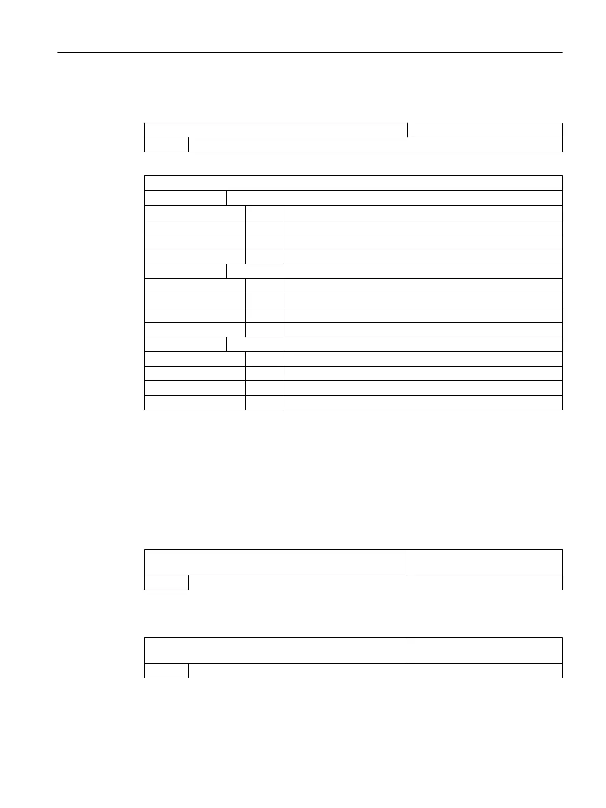
SD54632 $SNS_MEA_T_PROBE_ALLOW_AX_DIR[k] Axes and directions for "calibration"
= 133 Default value
Decimal place
ONES 1. Axis
= 0 axis not possible
= 1 only minus direction
= 2 only plus direction
= 3 both directions
TENS 2. Axis
= 0 axis not possible
= 1 only minus direction
= 2 only plus direction
= 3 both directions
HUNDREDS 3. Axis
= 0 axis not possible
= 1 only minus direction
= 2 only plus direction
= 3 both directions
Example
If the general setting
data SD54632 $SNS_MEA_T_PROBE_ALLOW_AX_DIR[k] has the value
123, the tool probe is calibrated as follows in the G17 plane:
● X in both directions
● Y only in plus direction
● Z only in minus direction
SD54631 $MNS_MEA_T_PROBE_DIAM_LENGTH[k] Effective diameter of the tool probe
for length measurement.
= 0 Default value
General cycle machine/setting data for tool probe
MD51780 $MNS_J_MEA_T_PROBE_DIAM_RAD[k] Effective diameter of the tool probe
for radius measurement.
= 0 Default value
Configuring cycles
7.9 Measuring cycles and measurement functions
SINUMERIK Operate
Commissioning Manual, 10/2015, 6FC5397-3DP40-5BA3 181

 Loading...


