132 007-4486-001
Chapter 5: Ordering, Removing, Upgrading, Installing Replacement Parts
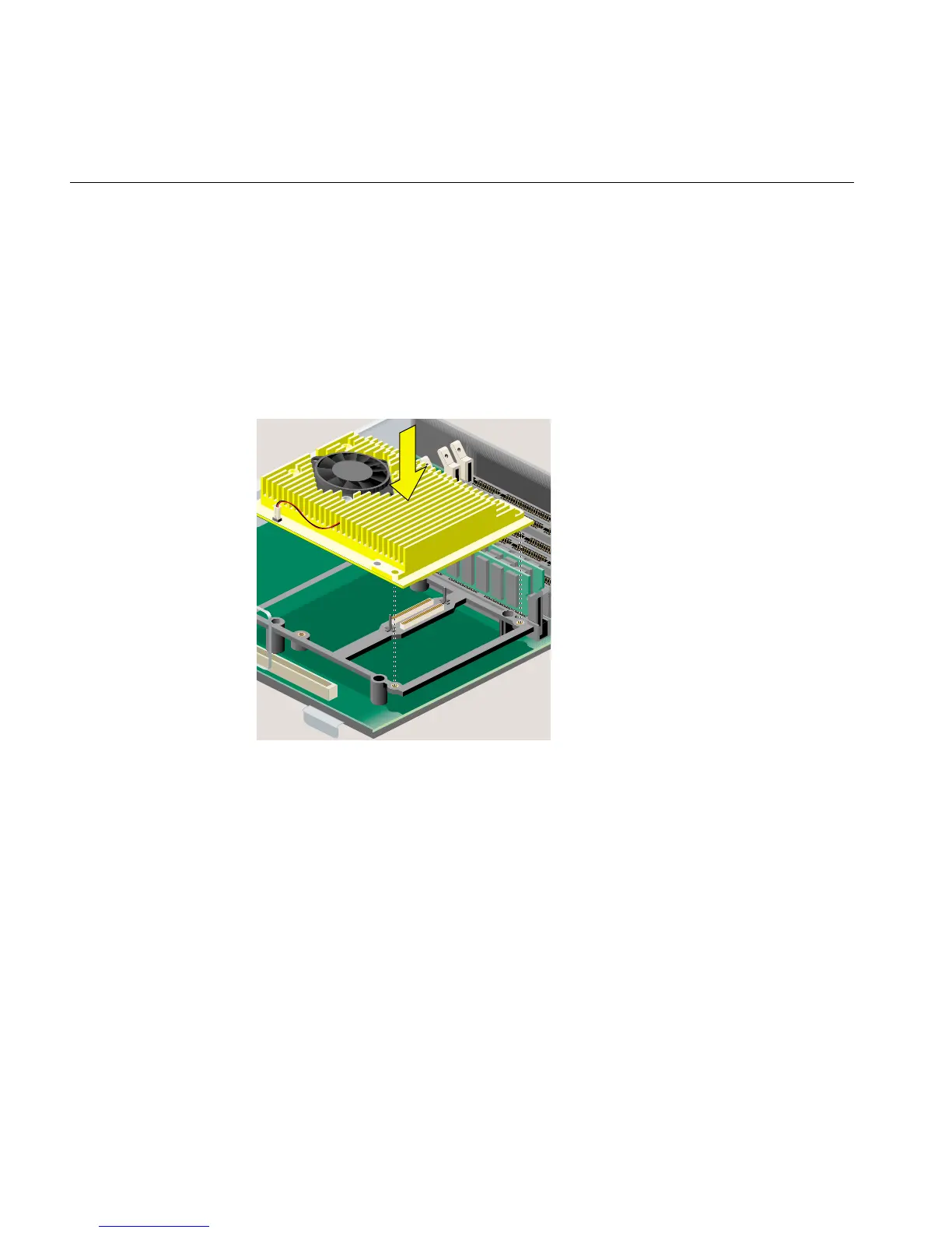
9. Install the replacement R12000class CPU module (Figure 5-15), as follows:
• Align the screw holes on the CPU module with the screw holes on the CPU
support. Make sure the CPU module is positioned correctly before pressing
down.
• Press down gently on the CPU module until it is securely seated. You hear a
click as it connects.
• Insert and tighten the four Phillips screws in the locations shown.
Figure 5-15 Securing the R12000class CPU Module
10. Remove the wrist strap.
11. Replace the PCI tray in the system module, as follows:
• Lower the PCI tray, engaging it on the metal rear panel of the system module
(Figure 5-16).
• Insert the PCI connector beneath the tray into the slot on the system module.
• Once the connector is aligned, push down firmly until it is completely seated.