56 007-4486-001
Chapter 2: Installing or Removing Memory and Option Boards
7. Push the board down into the socket firmly until it clicks and the connectors are
completely seated. Look from the side as shown in Figure 2-34.
Figure 2-34 Seating the Option Board Viewed from the Side
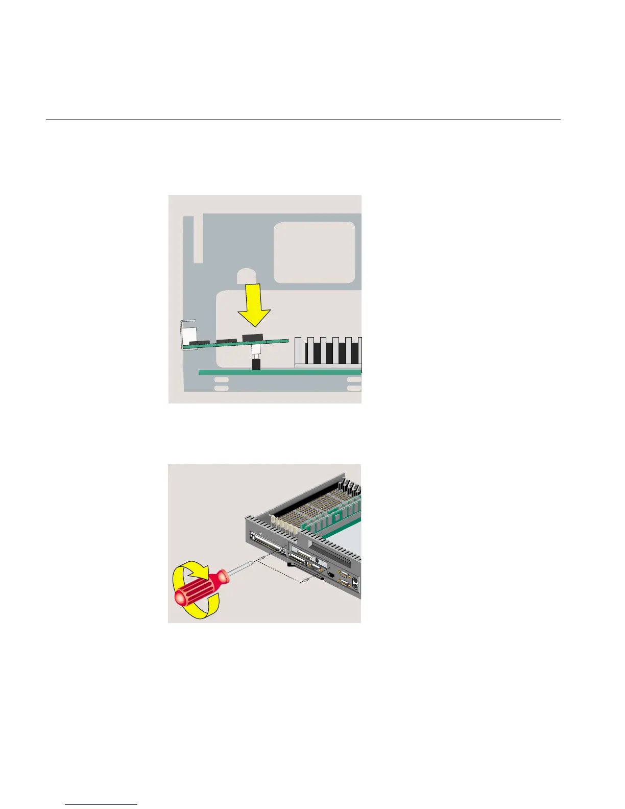
8. Insert and tighten two screws in the locations shown (Figure 2-35).
Figure 2-35 Installing the Two Screws