40 007-4486-001
Chapter 2: Installing or Removing Memory and Option Boards
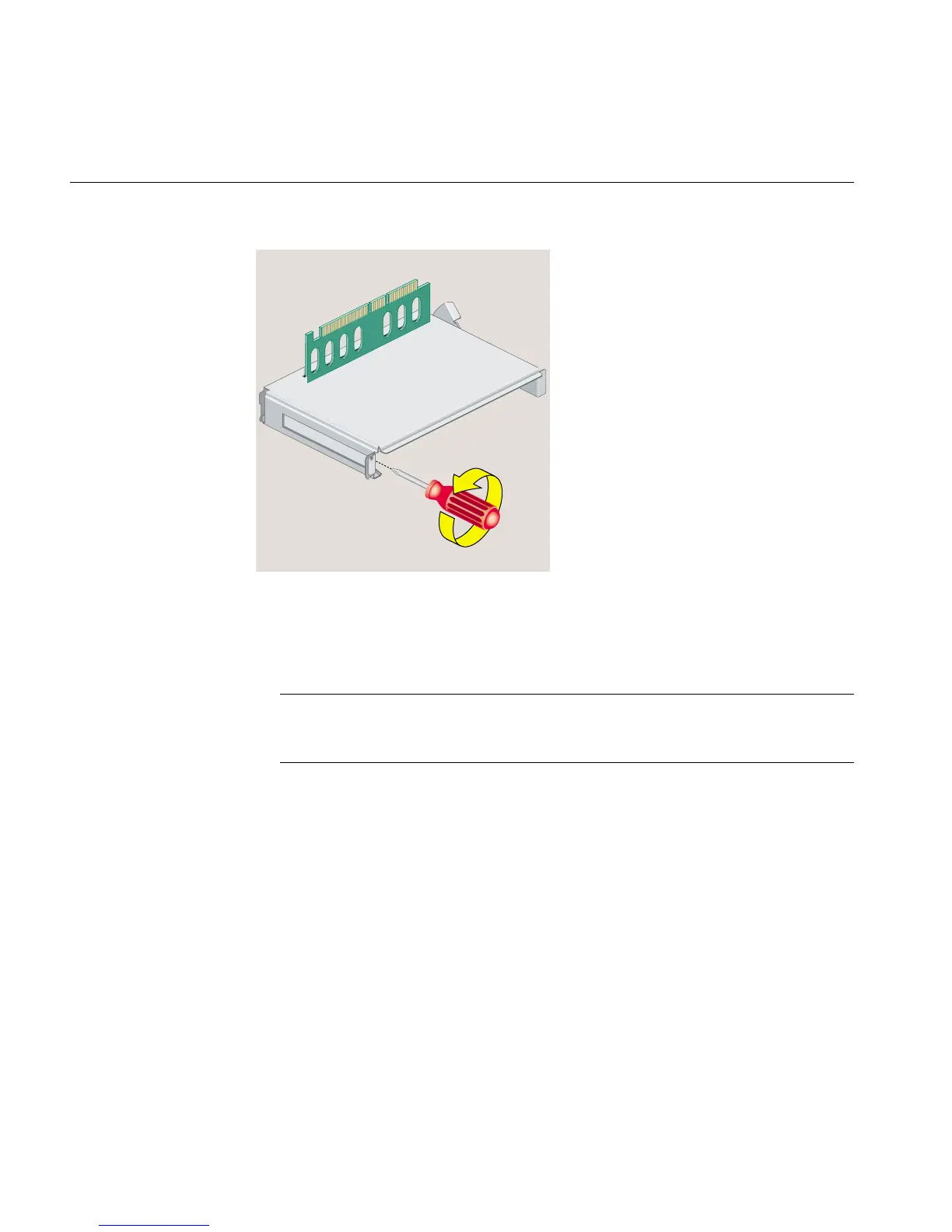
Figure 2-15 Removing the Screw and Filler Panel
5. Slide the PCI board into the tray and push the PCI connector firmly into the slot
(Figure 2-16). Make sure it is completely seated. You should hear a click as it is
seated. You may have to use some pressure.
Note: PCI boards with extra long I/O connectors may be difficult to install. In this
case, slide the board into the tray at an angle, inserting the side with the I/O
connector first, and then rotate in the other side.
6. Replace the screw and tighten it (Figure 2-16).