46 007-4486-001
Chapter 2: Installing or Removing Memory and Option Boards
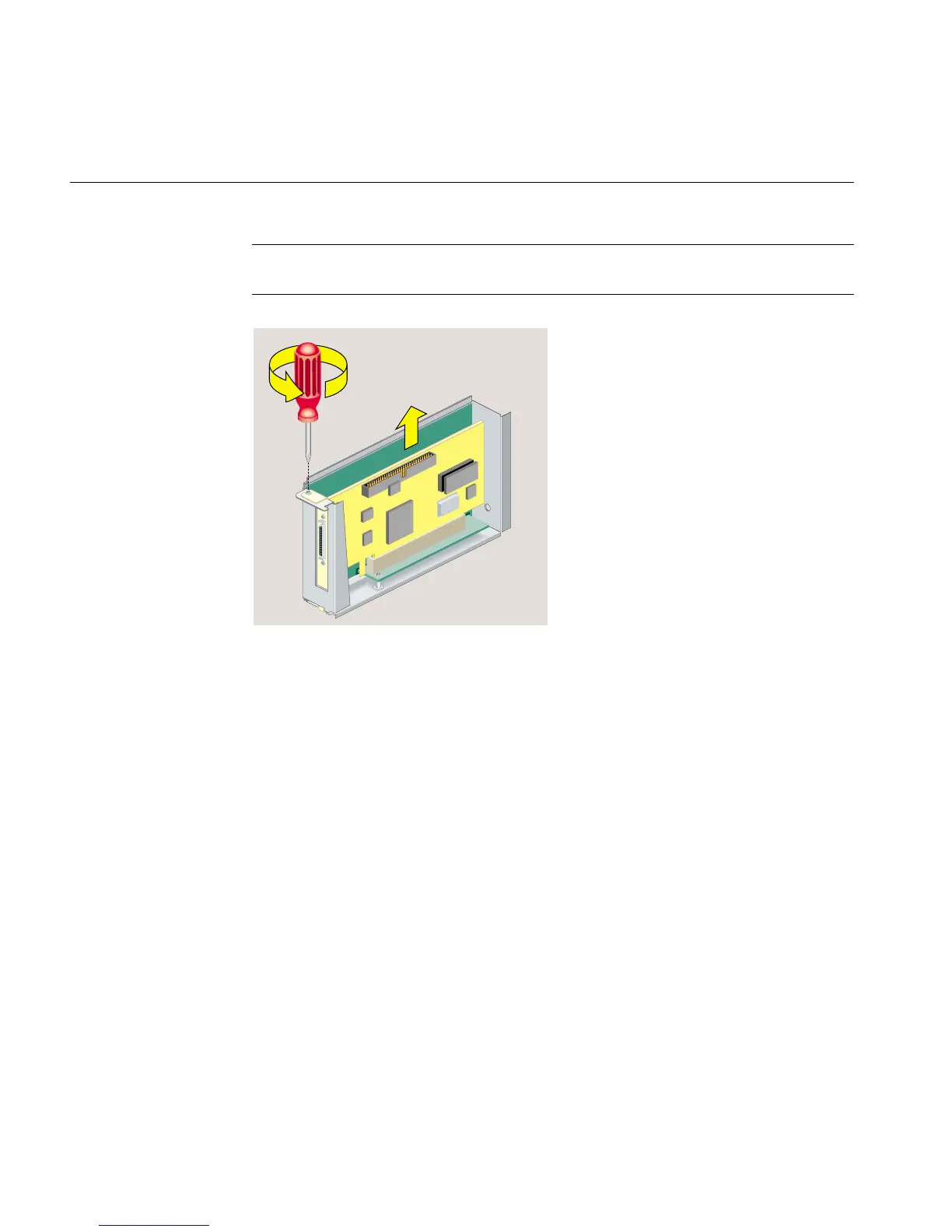
Note: If the PCI board has an extra long I/O connector, pivot up the side of the board
without the long I/O connector first. Then slide out the side with the I/O connector.
Figure 2-22 Removing the Screw and the PCI Board
5. If you want to install another PCI board, see “Installing a PCI Board in an
RM7000class Workstation”. If not, replace the filler panel and screw (Figure 2-23).
(You removed the panel and screw when you installed the board.)