Serial audio interface (SAI) RM0440
1854/2126 RM0440 Rev 4
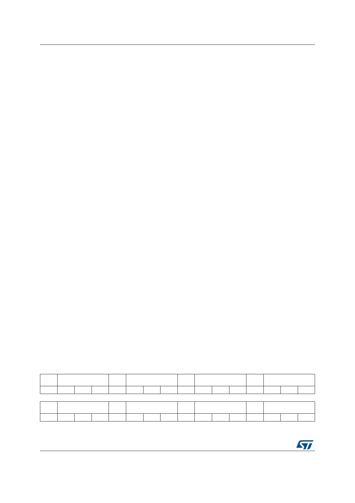
40.5.18 SAI PDM delay register (SAI_PDMDLY)
Address offset: 0x0048
Reset value: 0x0000 0000
Bit 10 CKEN3: Clock enable of bitstream clock number 3
This bit is set and cleared by software.
0: SAI_CK3 clock disabled
1: SAI_CK3 clock enabled
Note: It is not recommended to configure this bit when PDMEN = 1.
Bit 9 CKEN2: Clock enable of bitstream clock number 2
This bit is set and cleared by software.
0: SAI_CK2 clock disabled
1: SAI_CK2 clock enabled
Note: It is not recommended to configure this bit when PDMEN = 1.
Bit 8 CKEN1: Clock enable of bitstream clock number 1
This bit is set and cleared by software.
0: SAI_CK1 clock disabled
1: SAI_CK1 clock enabled
Note: It is not recommended to configure this bit when PDMEN = 1.
Bits 7:6 Reserved, must be kept at reset value.
Bits 5:4 MICNBR[1:0]: Number of microphones
This bit is set and cleared by software.
00: Configuration with 2 microphones
01: Configuration with 4 microphones
10: Configuration with 6 microphones
11: Configuration with 8 microphones
Note: It is not recommended to configure this field when PDMEN = 1.*
Bits 3:1 Reserved, must be kept at reset value.
Bit 0 PDMEN: PDM enable
This bit is set and cleared by software. This bit allows to control the state of the PDM interface block.
Make sure that the SAI in already operating in TDM master mode before enabling the PDM interface.
0: PDM interface disabled
1: PDM interface enabled
31 30 29 28 27 26 25 24 23 22 21 20 19 18 17 16
Res. DLYM4R[2:0] Res. DLYM4L[2:0] Res. DLYM3R[2:0] Res. DLYM3L[2:0]
rw rw rw rw rw rw rw rw rw rw rw rw
1514131211109876543210
Res. DLYM2R[2:0] Res. DLYM2L[2:0] Res. DLYM1R[2:0] Res. DLYM1L[2:0]
rw rw rw rw rw rw rw rw rw rw rw rw

 Loading...