RM0440 Rev 4 389/2126
RM0440 Peripherals interconnect matrix
401
Timers (TIMx, HRTIM) and EXTI can be used as triggering event to start a DAC conversion.
Triggering signals
The output (from timer) is on signal TIMx_TRGO directly connected to corresponding DAC
inputs.
Selection of input triggers on DAC is provided in Section 22.4.7: DAC trigger selection
(single and dual mode).
Active power mode
Run, Sleep, Low-power run, Low-power sleep.
11.3.5 From HSE, LSE, LSI, HSI16, MCO, RTC to timer (TIMx)
See please Table 75: Interconnect 4 and Table 73: Interconnect 2
External clocks (HSE, LSE), internal clocks (LSI, HSI16), microcontroller output clock
(MCO), GPIO and RTC wakeup interrupt can be used as input to timer (TIMx).
This allows to calibrate the HSI16 and precisely measure the LSI oscillator frequency.
When Low Speed External (LSE) oscillator is used, no additional hardware connections are
required.
This feature is described in Section 7.2.16: Internal/external clock measurement with
TIM5/TIM15/TIM16/TIM17.
Active power mode
Run, Sleep, Low-power run, Low-power sleep.
12
hrtim_dac_
reset_trg4
hrtim_step
_trig4
hrtim_dac_
reset_trg4
hrtim_step
_trig4
hrtim_dac
_reset_trg
4
hrtim_step
_trig4
hrtim_dac
_reset_trg
4
hrtim_step
_trig4
13
hrtim_dac_
reset_trg5
hrtim_step
_trig5
hrtim_dac_
reset_trg5
hrtim_step
_trig5
hrtim_dac
_reset_trg
5
hrtim_step
_trig5
hrtim_dac
_reset_trg
5
hrtim_step
_trig5
14
hrtim_dac_
reset_trg6
hrtim_step
_trig6
hrtim_dac_
reset_trg6
hrtim_step
_trig6
hrtim_dac
_reset_trg
6
hrtim_step
_trig6
hrtim_dac
_reset_trg
6
hrtim_step
_trig6
15
hrtim_dac_
trg1
-
hrtim_dac_
trg2
-
hrtim_dac
_trg3
-
hrtim_dac
_trg1
-
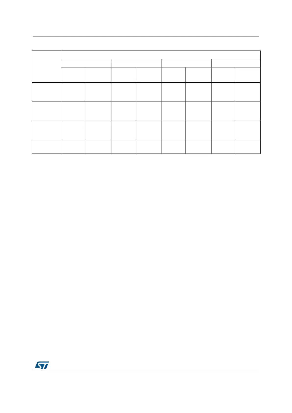
Table 66. Interconnect 20 (continued)
DAC trigger
selection
(TSELx[3:0],
STRSTTRIG
SELx[3:0])
DAC triggers signals assignment
DAC1 DAC2 DAC3 DAC4
Update/
reset
Inc
Update/
reset
Inc
Update
/reset
Inc
Update/
reset
Inc
 Loading...


