B.3 Parameter Table
YASKAWA ELECTRIC SIEP C710616 27G YASKAWA AC Drive A1000 Technical Manual 495
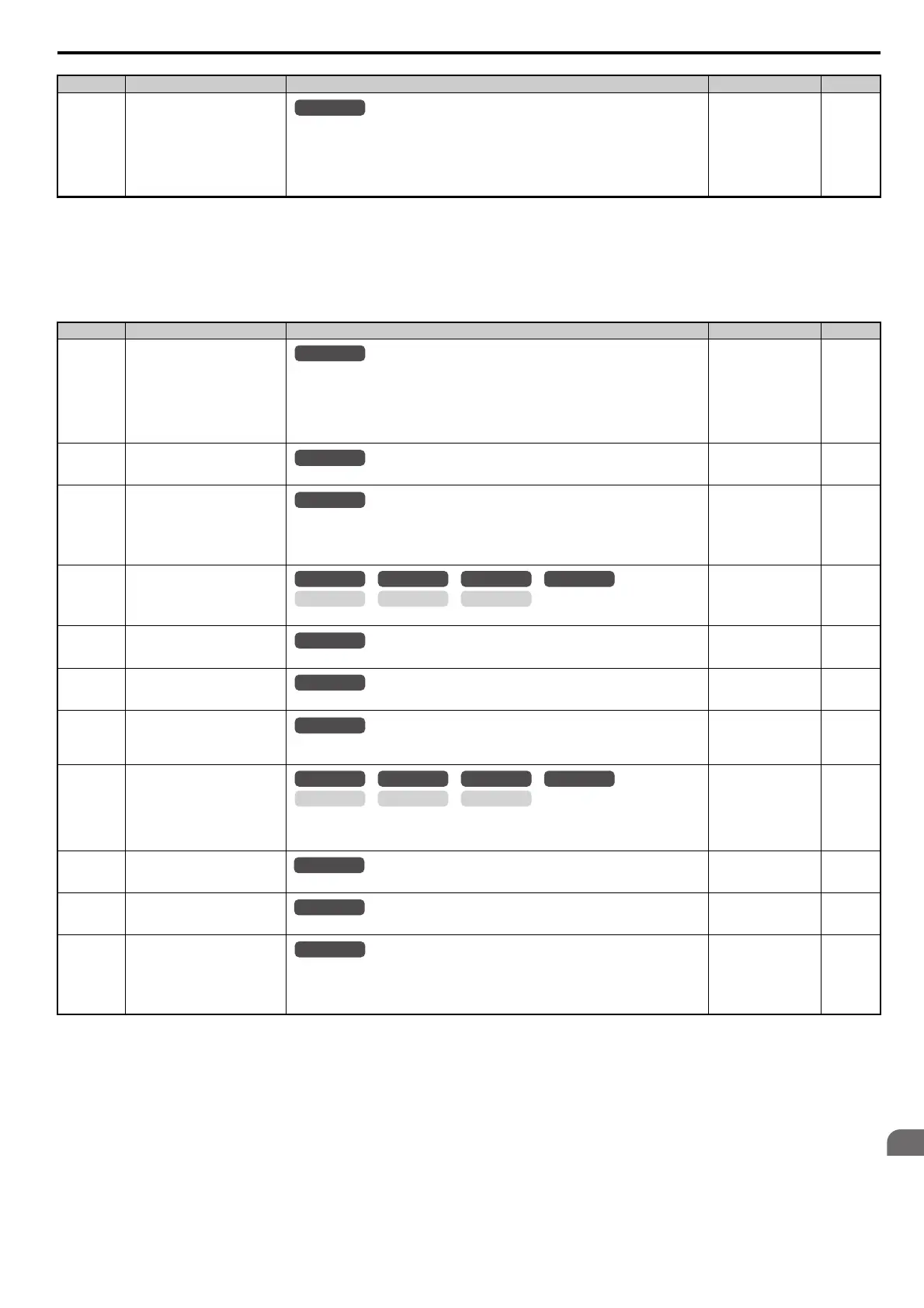
L2: Momentary Power Loss Ride-Thru
L1-20
(445H)
Operation at Motor Overheat
(oH5)
Determines what action the drive should take when a motor overheat fault occurs (oH5).
0: Ramp to stop
1: Coast to stop
2: Fast Stop (decelerate to stop using the deceleration time in C1-09)
3: Alarm only ("oH5" will flash)
Note: This parameter is available in models CIMR-A4A0930 and 4A1200.
Default: 1
Min: 0
Max: 3
274
<9> Default setting is determined by the drive model (o2-04) and duty selection (C6-01).
<10> Default setting is determined by the control mode (A1-02).
<19> Display is in the following units.
CIMR-A2A0004 to 2A0040, CIMR-A4A0002 to 4A0023: 0.01 A units
CIMR-A2A0056 to 2A0312, CIMR-A4A0031 to 4A0675: 0.1 A units
No. (Addr.) Name Description Setting Page
L2-01
(485H)
<9> Default setting is determined by the drive model (o2-04) and duty selection (C6-01).
<12> Setting range value is dependent on the units selected for the accel/decel time (C1-10). When C1-10 = 0 (units of 0.01 s), the setting range
becomes 0.00 to 600.00 s.
<18> Values shown here are for 200 V class drives. Double the value when using a 400 V class drive.
<33> Default setting value is dependent on the setting for the input voltage (E1-01).
Momentary Power Loss Operation
Selection
0: Disabled. Drive trips on (Uv1) fault when power is lost.
1: Recover within the time set in L2-02. Uv1 will be detected if power loss is longer than L2-02.
2: Recover as long as CPU has power. Uv1 is not detected.
3: KEB deceleration for the time set to L2-02.
4: KEB deceleration as long as CPU has power.
5: KEB deceleration to stop.
Default: 0
Min: 0
Max: 5
274
L2-02
(486H)
Momentary Power Loss Ride-Thru
Time
Sets the Power Loss Ride-Thru time. Enabled only when L2-01 = 1 or 3.
Default:
<9>
Min: 0.0 s
Max: 25.5 s
279
L2-03
(487H)
Momentary Power Loss Minimum
Baseblock Time
Sets the minimum wait time for residual motor voltage decay before the drive output
reenergizes after performing Power Loss Ride-Thru.
Increasing the time set to L2-03 may help if overcurrent or overvoltage occur during Speed
Search or during DC Injection Braking.
Default:
<9>
Min: 0.1 s
Max: 5.0 s
279
L2-04
(488H)
Momentary Power Loss Voltage
Recovery Ramp Time
Sets the time for the output voltage to return to the preset V/f pattern during Speed Search.
Default: <9>
Min: 0.0 s
Max: 5.0 s
279
L2-05
(489H)
Undervoltage Detection Level
(Uv)
Sets the DC bus undervoltage trip level.
Default:
<18> <33>
Min: 150 Vdc
Max: 210 Vdc
<18>
280
L2-06
(48AH)
KEB Deceleration Time
Sets the time required to decelerate from the speed when KEB was activated to zero speed.
Default: 0.00 s
Min: 0.00 s
Max: 6000.0 s
<12>
280
L2-07
(48BH)
KEB Acceleration Time
Sets the time to accelerate to the frequency reference when momentary power loss is over. If set
to 0.0, the active acceleration time (C1-01, C1-03, C1-05, or C1-07) is used.
Default: 0.00 s
Min: 0.00 s
Max: 6000.0 s
<12>
280
L2-08
(48CH)
Frequency Gain at KEB Start
Sets the percentage of output frequency reduction at the beginning of deceleration when the
KEB Ride-Thru function is started.
Reduction = (slip frequency before KEB) L2-08/100 2
Default: 100%
Min: 0%
Max: 300%
280
L2-10
(48EH)
KEB Detection Time (Minimum
KEB Time)
Sets the time to perform KEB Ride-Thru.
Default: 50 ms
Min: 0 ms
Max: 2000 ms
280
L2-11
(461H)
DC Bus Voltage Setpoint during
KEB
Sets the desired value of the DC bus voltage during KEB Ride-Thru.
Default:
<18> <33>
Min: 150 Vdc
Max: 400 Vdc
<18>
280
L2-29
(475H)
KEB Method Selection
0: Single Drive KEB Ride-Thru 1
1: Single Drive KEB Ride-Thru 2
2: System KEB Ride-Thru 1
3: System KEB Ride-Thru 2
Default: 0
Min: 0
Max: 3
281
No. (Addr.) Name Description Setting Page
All Modes
All Modes
All Modes
All Modes
OLV/PM AOLV/PM
CLV
V/f w/PG
CLV/PM
V/f OLV
All Modes
All Modes
OLV/PM AOLV/PM
CLV
V/f w/PG
CLV/PM
V/f OLV
All Modes