B.3 Parameter Table
496 YASKAWA ELECTRIC SIEP C710616 27G YASKAWA AC Drive A1000 Technical Manual
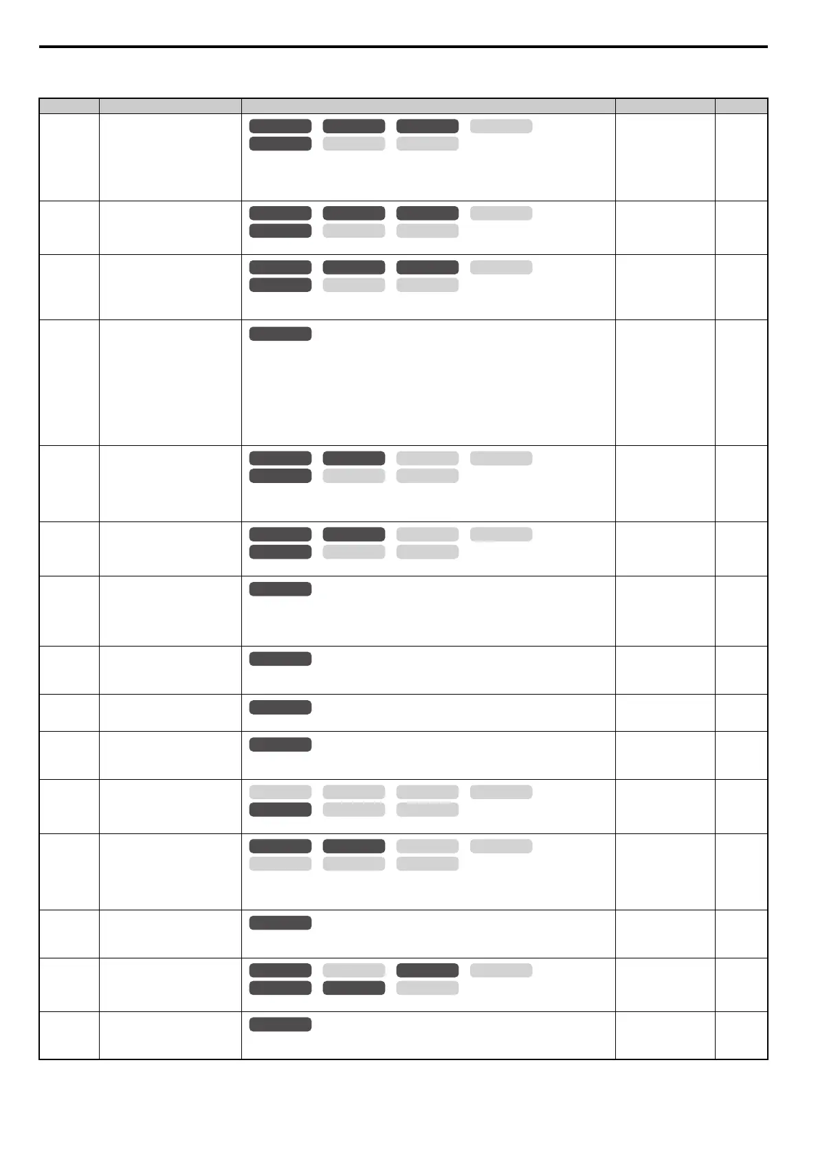
L3: Stall Prevention
No. (Addr.) Name Description Setting Page
L3-01
(48FH)
Stall Prevention Selection during
Acceleration
0: Disabled.
1: General purpose. Acceleration is paused as long as the current is above the L3-02 setting.
2: Intelligent. Accelerate in the shortest possible time without exceeding the L3-02 level.
Note: Setting 2 is not available when using OLV/PM.
Default: 1
Min: 0
Max: 2
281
L3-02
(490H)
Stall Prevention Level during
Acceleration
Used when L3-01 = 1 or 2. 100% is equal to the drive rated current.
Default:
<35>
Min: 0%
Max: 150%
<35>
283
L3-03
(491H)
Stall Prevention Limit during
Acceleration
Sets Stall Prevention lower limit during acceleration when operating in the constant power
range. Set as a percentage of the drive’s rated current.
Default: 50%
Min: 0%
Max: 100%
283
L3-04
(492H)
Stall Prevention Selection during
Deceleration
0: Disabled. Deceleration at the active deceleration rate. An ov fault may occur.
1: General purpose. Deceleration is paused when the DC bus voltage exceeds the Stall
Prevention level.
2: Intelligent. Decelerate as fast as possible while avoiding ov faults.
3: Stall Prevention with braking resistor. Stall Prevention during deceleration is enabled in
coordination with dynamic braking.
4: Overexcitation Deceleration. Decelerates while increasing the motor flux.
5: Overexcitation Deceleration 2. Adjust the deceleration rate according to the DC voltage.
Note: The setting of 3 is not available with models CIMR-A4A0930 and 4A1200.
Default: 1
Min: 0
Max: 5
<34>
283
L3-05
(493H)
Stall Prevention Selection during
Run
0: Disabled. Drive runs at a set frequency. A heavy load may cause stalling.
1: Decel time 1. Uses the deceleration time set to C1-02 while Stall Prevention is performed.
2: Decel time 2. Uses the deceleration time set to C1-04 while Stall Prevention is performed.
Default: 1
Min: 0
Max: 2
284
L3-06
(494H)
Stall Prevention Level during Run
Enabled when L3-05 is set to 1 or 2. 100% is equal to the drive rated current.
Default:
<35>
Min: 30%
Max: 150%
<35>
285
L3-11
(4C7H)
Overvoltage Suppression Function
Selection
Enables or disables the ov suppression function, which allows the drive to change the output
frequency as the load changes to prevent an ov fault.
0: Disabled
1: Enabled
Default: 0
Min: 0
Max: 1
285
L3-17
(462H)
Target DC Bus Voltage for
Overvoltage Suppression and Stall
Prevention
Sets the desired value for the DC bus voltage during overvoltage suppression and Stall
Prevention during deceleration.
Default: 375 Vdc
<18>
<33>
Min: 150 Vdc
Max: 400 Vdc
<18>
286
L3-20
(465H)
DC Bus Voltage Adjustment Gain
Sets the proportional gain for KEB Ride-Thru, Stall Prevention, and overvoltage suppression.
Default:
<10>
Min: 0.00
Max: 5.00
286
L3-21
(466H)
Accel/Decel Rate Calculation Gain
Sets the proportional gain used to calculate the deceleration rate during KEB Ride-Thru, ov
suppression function, and Stall Prevention during deceleration (L3-04 = 2).
Default:
<10>
Min: 0.10
Max: 10.00
286
L3-22
(4F9H)
Deceleration Time at Stall
Prevention during Acceleration
Sets the deceleration time used for Stall Prevention during acceleration in OLV/PM.
Default: 0.0 s
Min: 0.0 s
Max: 6000.0 s
286
L3-23
(4FDH)
Automatic Reduction Selection for
Stall Prevention during Run
0: Sets the Stall Prevention level set in L3-06 that is used throughout the entire frequency range.
1: Automatic Stall Prevention level reduction in the constant output range. The lower limit
value is 40% of L3-06.
Default: 0
Min: 0
Max: 1
287
L3-24
(46EH)
Motor Acceleration Time for
Inertia Calculations Sets the time needed to accelerate the uncoupled motor at rated torque from stop to the
maximum frequency.
Default:
<8> <9> <14>
Min: 0.001 s
Max: 10.000 s
287
L3-25
(46FH)
Load Inertia Ratio
Sets the ratio between the motor and machine inertia.
Default: 1.0
Min: 1.0
Max: 1000.0
287
L3-26
(455H)
Additional DC Bus Capacitors
When DC bus capacitors have been added externally, be sure to add those values to the internal
capacitor table for proper DC bus calculations.
Default: 0 F
Min: 0 F
Max: 65000 F
288
OLV/PM AOLV/PM
CLV
V/f w/PG
CLV/PM
V/f OLV
OLV/PM AOLV/PM
CLV
V/f w/PG
CLV/PM
V/f OLV
OLV/PM AOLV/PM
CLV
V/f w/PG
CLV/PM
V/f OLV
All Modes
OLV/PM AOLV/PM
CLV
V/f w/PG
CLV/PM
V/f OLV
OLV/PM AOLV/PM
CLV
V/f w/PG
CLV/PM
V/f OLV
All Modes
All Modes
All Modes
All Modes
OLV/PM AOLV/PM
CLV
V/f w/PG
CLV/PM
V/f OLV
OLV/PM AOLV/PM
CLV
V/f w/PG
CLV/PM
V/f OLV
All Modes
OLV/PM AOLV/PM
CLV
V/f w/PG
CLV/PM
V/f OLV
 Loading...


