Mechanical & Electrical
Installation
2
2.9 Change the Drive Enclosure Type
YASKAWA ELECTRIC SIEP C710617 05F YASKAWA AC Drive GA700 Technical Manual 63
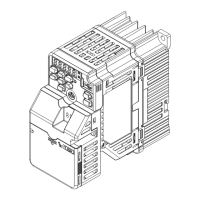
A - Front of drive B - Screw holes on bottom
Figure 2.55 Locations of Screw Holes on Bottom of Conduit Bracket 1
4. Align the screw holes on conduit bracket 3 with the screw holes on conduit bracket 2.
Tighten the screws to a tightening torque of 0.98 N∙m to 1.33 N∙m (8.67 lb.∙in. to 11.77 lb.∙in.) and lift
bracket 3 a short distance.
A - Conduit bracket 3
Figure 2.56 Attach Conduit Bracket 3
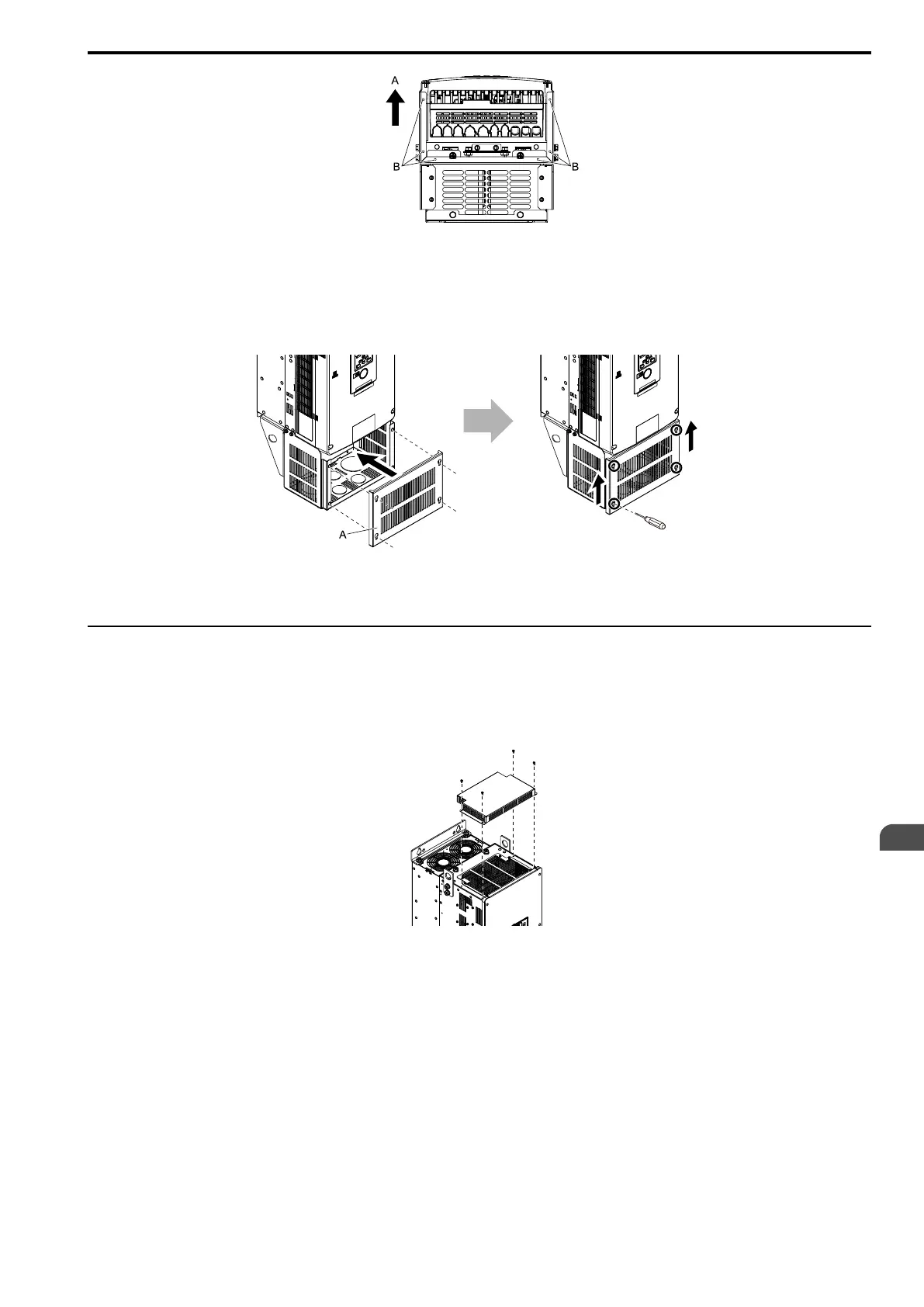
◆ Attach the Protective Cover (Procedure E)
■ Attach the Top Protective Cover
Align the screw holes of the top protective cover with the screw holes on the top of the drive.
Tighten the screws to a tightening torque of 0.98 N∙m to 1.33 N∙m (8.67 lb.∙in. to 11.77 lb.∙in.) to attach the cover.
Figure 2.57 Attach the Top Protective Cover