2.15 Control I/O Connections
116 YASKAWA ELECTRIC SIEP C710617 05F YASKAWA AC Drive GA700 Technical Manual
Terminal
Types of Output
Signals
Jumper Switch S5
Parameters
No. Signal Level
FM
Voltage output
(Default)
H4-07
0: 0 V to 10 V
1: -10 V to +10 V
Current output 2: 4 mA to 20 mA
AM
Voltage output
(Default)
H4-08
0: 0 V to 10 V
1: -10 V to +10 V
Current output 2: 4 mA to 20 mA
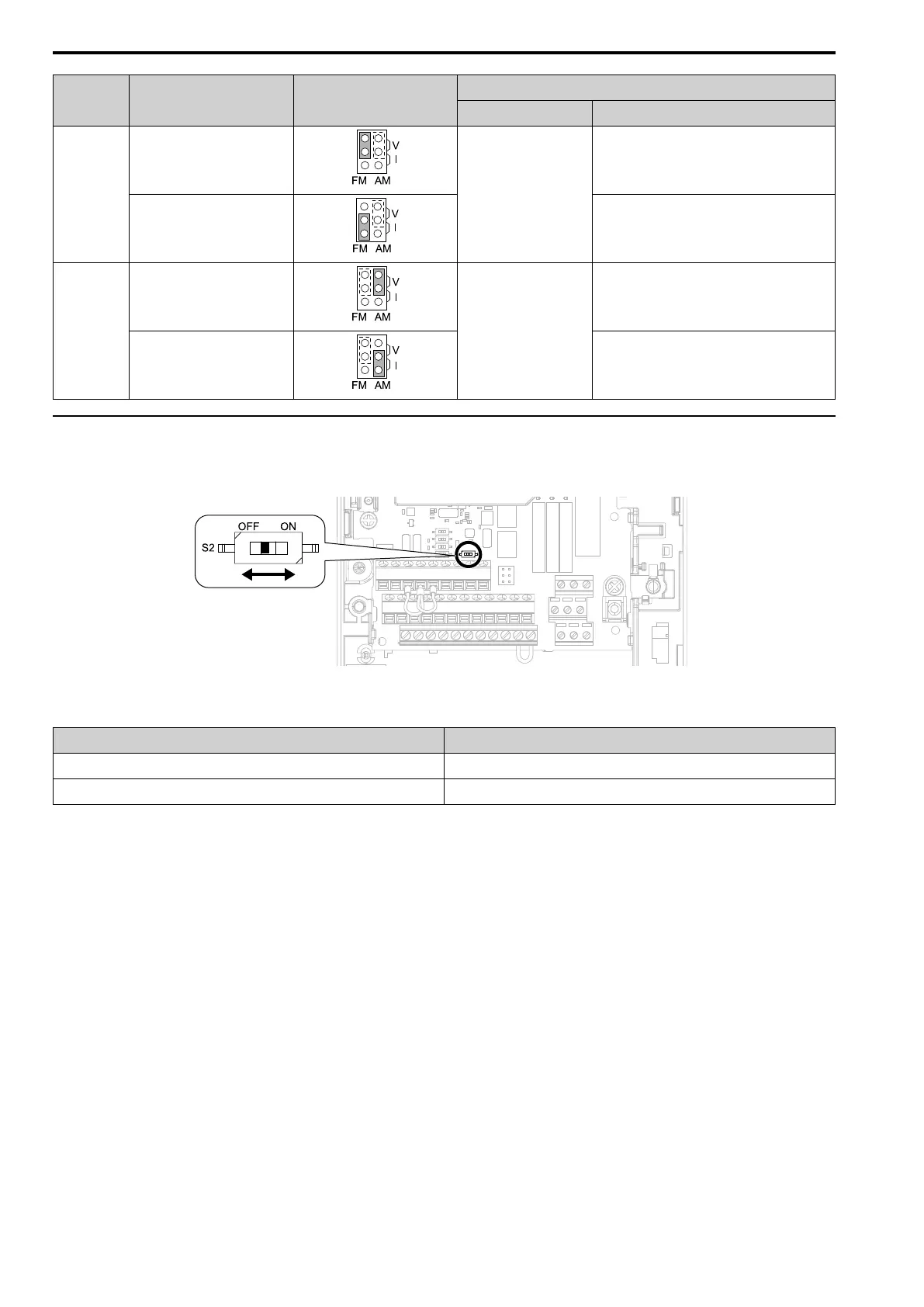
◆ Switch ON Termination Resistor for MEMOBUS/Modbus Communications
When the drive is the last slave in a MEMOBUS/Modbus communications, set DIP switch S2 to the ON position.
This drive has a built-in termination resistor for the RS-485 interface.
Figure 2.117 Location of DIP Switch S2
Table 2.29 MEMOBUS/Modbus Communications Termination Resistor Setting
DIP Switch S2 Description
ON The built-in termination resistor is ON.
OFF (Default) The built-in termination resistor is OFF.