Mechanical & Electrical
Installation
2
2.15 Control I/O Connections
YASKAWA ELECTRIC SIEP C710617 05F YASKAWA AC Drive GA700 Technical Manual 115
Termi
nal
Input
Signal
DIP Switch Settings Parameters
Switch Setting No. Signal Level
A3
Voltage
input
S1-3
V
(Default)
H3-05
0: 0 V to 10 V/0% to 100% (input impedance: 20 kΩ)
1: -10 V to +10 V/-100% to 100%
Current
input
I
2: 4 mA to 20 mA/0% to 100%
3: 0 mA to 20 mA/0% to 100% (input impedance: 250 Ω)
Note:
• Set H3-02, H3-10 = 0 [Terminal A1 Function Selection, Terminal A2 Function Selection = Frequency Reference] to set A1 and A2 to
frequency reference. The drive will add the analog input values together to make the frequency reference.
• Use tweezers or a jig with a tip width of approximately 0.8 mm (0.03 in.) to set DIP switches.
• Set DIP switch S4 to “AI” to use terminal A3 as an analog input (voltage/current) terminal. The default setting for DIP switch S4 is
“AI”.
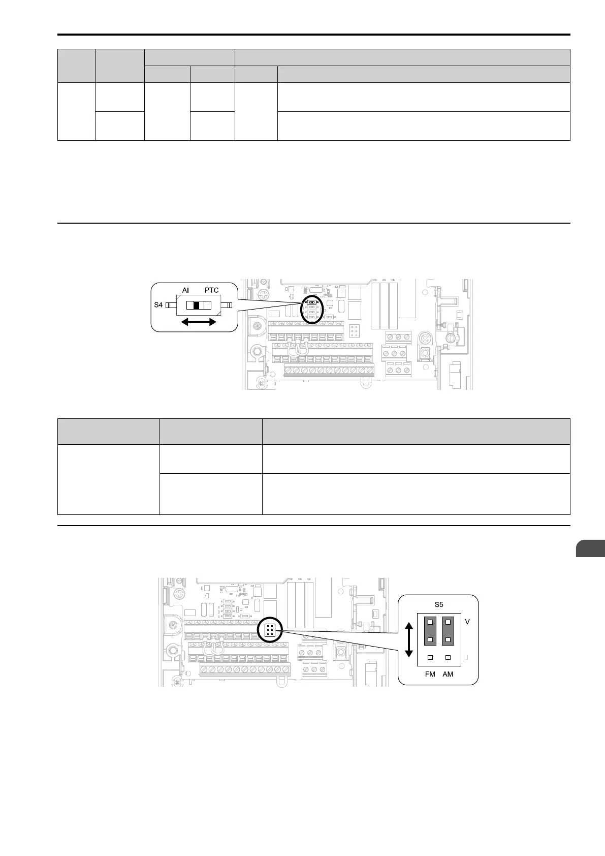
◆ Set MFAI Terminal A3 to PTC Input
Set terminal A3 as an MFAI or as the PTC input for motor overload protection.
Use DIP switch S4 to set the input function.
Figure 2.115 Location of DIP Switch S4
Terminal
Settings for DIP
Switches
Description
A3
AI
(Default)
Functions as an MFAI terminal.
Set H3-06 [Terminal A3 Function Selection] to select the input function.
PTC
Functions as the PTC input terminal.
Set H3-06 = E [Motor Temperature (PTC Input)].
Set S1-3 to “V” for voltage input.
◆ Set Output Signals for MFAO Terminals FM, AM
Set the signal type for terminals AM and FM to voltage or current output. Use jumper switch S5 and H4-07, H4-
08 [Terminal FM Signal Level Select, Terminal AM Signal Level Select] to set the signal type.
Figure 2.116 Location of Jumper Switch S5