Mechanical & Electrical
Installation
2
2.7 Install the Keypad to a Control Panel or Another Device
YASKAWA ELECTRIC SIEP C710617 05F YASKAWA AC Drive GA700 Technical Manual 45
2.7 Install the Keypad to a Control Panel or Another Device
◆ Operate the Keypad Apart from the Drive
You can remove the keypad from the drive and connect it to a remote control extension cable 3 m (9.8 ft) long to
make operation easier when you cannot access the drive. You can operate a drive that is in a control panel without
opening or closing the control panel door. To order optional accessories, contact Yaskawa or your nearest sales
representative.
◆ Connect the Keypad from a Remote Location
Use the information in Table 2.7 to install the keypad in the best location for your application.
Table 2.7 Keypad Installation Method
Installation Method Description
Required Tools and Installation
Support Sets
Outside the control panel
Simplified installation is possible. Separately
sold installation support sets are not
necessary.
Phillips screwdriver #2 (M3)
Inside the control panel
Keypad does not extend farther than the
front of the control panel.
• Phillips screwdriver #2 (M3, M4)
• Installation support set A (for mounting
with screws, model: 900-192-933-001)
• Phillips screwdriver #2 (M3)
• Wrench (M4)
• Installation support set B (for mounting
with nut clamp, model: 900-192-933-002)
Note:
Installation support sets are sold separately. If there are weld studs inside the control panel, use installation support set B.
NOTICE: Do not let unwanted objects, for example metal shavings or wire clippings, fall into the drive during drive installation
and project construction. Put a temporary cover over the top of the drive during installation. Remove the temporary cover before
start-up or the drive will overheat. Failure to obey can cause damage to the drive.
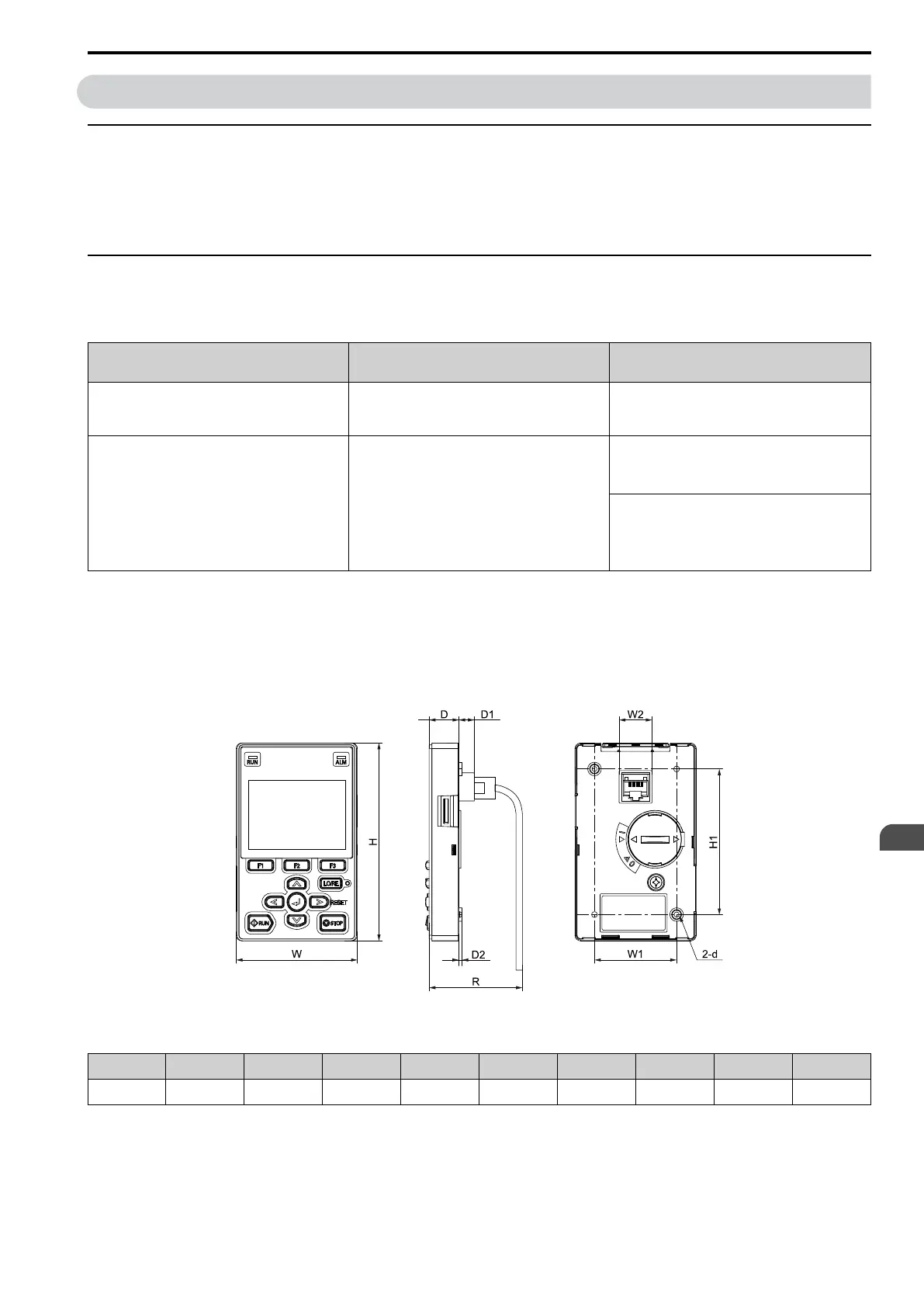
■ External Dimensions of Keypad
Figure 2.10 Exterior and Mounting Dimensions
Table 2.8 Exterior Dimensions (mm)
W H D D1 D2 R
*1
W1 W2 H1 d
65 106 16 8.2 1.6 53.8 44 15 78 M3
*1 Minimum bending radius