2.14 Control Circuit Wiring
112 YASKAWA ELECTRIC SIEP C710617 05F YASKAWA AC Drive GA700 Technical Manual
3. Put the cable through the clearance in the wiring cover.
Figure 2.110 Control Circuit Wiring
4. Install the LED status ring board, front cover, and the keypad to their initial positions.
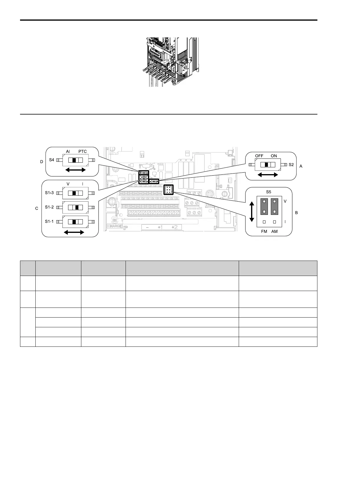
◆ Switches and Jumpers on the Terminal Board
The terminal board has switches to adapt the drive I/Os to the external control signals as shown in Figure 2.111.
Set the switches to select the functions for each terminal.
Figure 2.111 Locations of Switches
Table 2.27 I/O Terminals and Switches Functions
Posi
tion
Switch Terminal Function Default Setting
A DIP switch S2 -
Enables and disables the MEMOBUS/Modbus
communications termination resistor.
OFF
B Jumper switch S5 FM, AM
Sets terminals FM and AM to voltage or current
output.
FM: V (voltage output)
AM: V (voltage output)
C
DIP switch S1-1 A1 Selects the input signal type (voltage/current). V (voltage input)
DIP switch S1-2 A2 Selects the input signal type (voltage/current). I (current input)
DIP switch S1-3 A3 Selects the input signal type (voltage/current). V (voltage input)
D Dip switch S4 A3 Selects MFAI or PTC input. AI (analog input)