2.14 Control Circuit Wiring
110 YASKAWA ELECTRIC SIEP C710617 05F YASKAWA AC Drive GA700 Technical Manual
◆ Wiring the Control Circuit Terminal
WARNING! Electrical Shock Hazard. Do not remove covers or touch circuit boards while the drive is energized. Failure to obey
can cause death or serious injury.
NOTICE: Isolate control circuit wiring from main circuit wiring (terminals R/L1, S/L2, T/L3, B1, B2, U/T1, V/T2, W/T3, -, +1, +2)
and other high-power wiring. Incorrect wiring procedures could cause drive malfunction because of electrical interference.
NOTICE: Isolate contact output terminals MA, MB, MC and M1-M6 from other control circuit wiring. The drive and connected
equipment will malfunction or the drive can trip because of incorrect wiring.
NOTICE: Use a class 2 power supply when connecting to the control terminals. Refer to NEC Article 725 Class 1, Class 2, and
Class 3 Remote-Control, Signaling, and Power Limited Circuits for requirements concerning class 2 power supplies. Improper
application of peripheral devices could result in drive performance degradation due to improper power supply.
NOTICE: Insulate wire shields with tape or shrink tubing to prevent contact with other signal lines or equipment. Incorrect wiring
procedures could cause the drive or connected equipment to malfunction because of short circuits.
NOTICE: Connect the shield of shielded cable to the applicable ground terminal. Incorrect equipment grounding could cause
the drive or connected equipment to malfunction or to trip again and again.
Correctly ground the drive terminals and complete main circuit wiring before you wire the control circuit.
Remove the keypad and front cover.
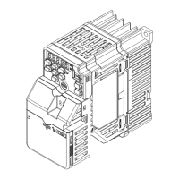
1. Push in on the tabs on the both sides of the LED status ring board to release the board from the bracket.
Pull the board forward to remove it.
NOTICE: Make sure that the LED status ring board is safe after you remove it from the bracket. Failure to obey will
cause damage to the LED status ring board.
Note:
You can temporarily store the LED status ring board with the temporary placement holes on the drive. The location of the
temporary placement holes changes by drive model.
A - Drive front
B - LED status ring board
C - Temporary placement holes
Figure 2.105 Remove the LED Status Ring Board
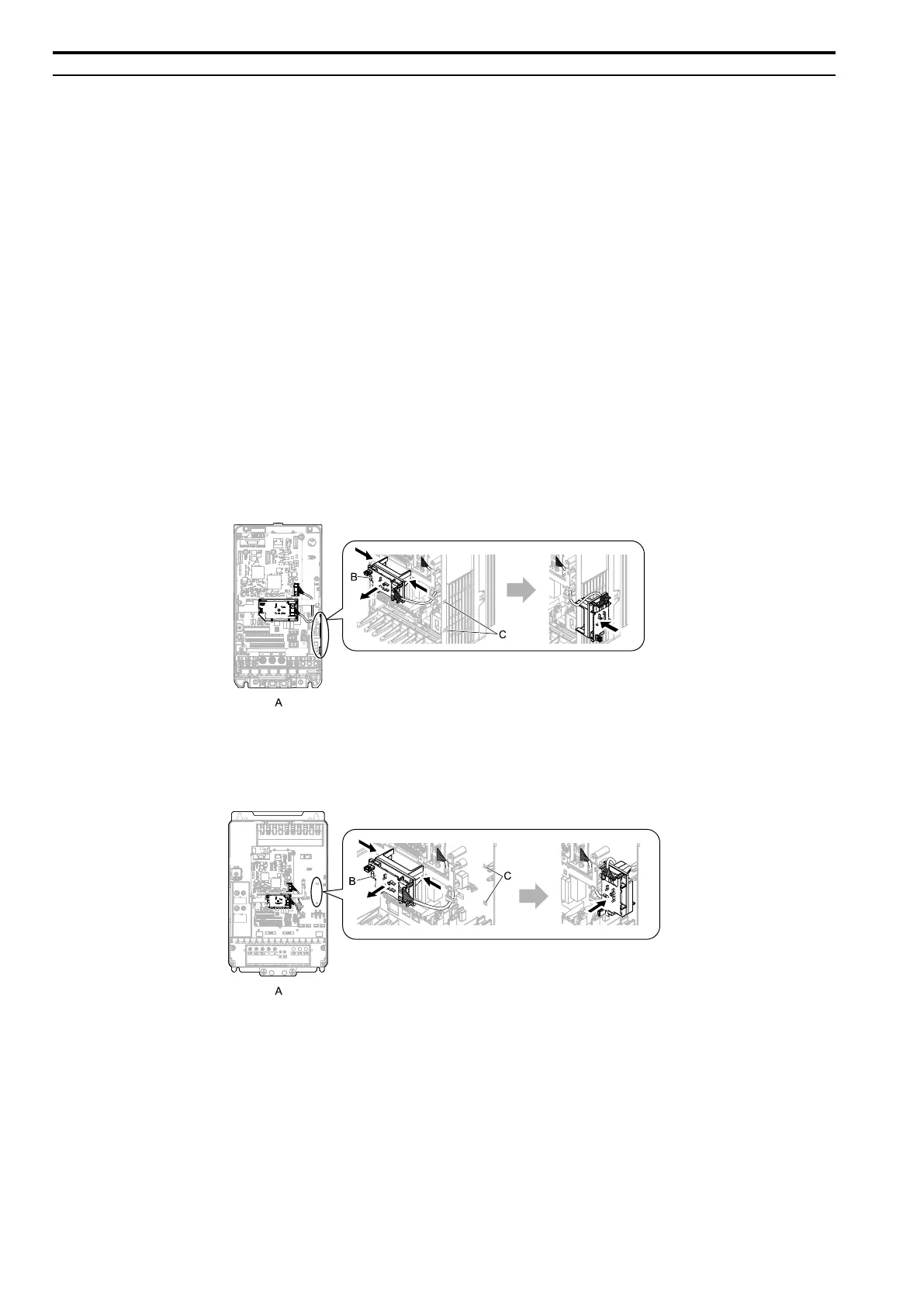
A - Drive front
B - LED status ring board
C - Temporary placement holes
Figure 2.106 Remove the LED Status Ring Board