10-82 IM 701450-01E
Explanation
This section explains the setup procedure for analyzing or searching the SPI Bus signal
while displaying the signal.
SPI Signal Analysis and Search Function
Analysis Function
When waveform acquisition is stopped, the signal data stored to the acquisition memory
(including the data stored as history waveforms) can be analyzed. Analysis is performed
at the byte level (8 bits) by synchronizing to the clock signal. The analyzed data is listed
at the bottom of the screen. The analysis data can be displayed in hexadecimal or
binary. The analysis data and signal can be displayed simultaneously.
Search Function
Data that matches a specified determination pattern can be searched from the analysis
data (forward search and backward search), and the data that is found can be displayed
expanded on the zoom display. You can set the determination pattern in hexadecimal or
binary and the data length in the range of 1 to 8 bytes. You can also search indefinite
data.
12
3
45678
Analysis data
00
0
01000
11
0
0010
0
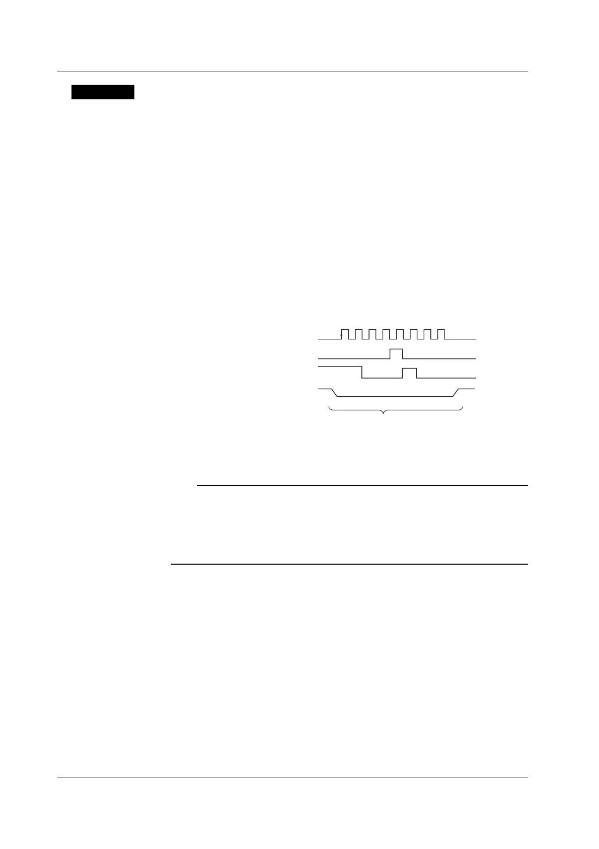
Clock signal on the SPI Bus
Output data signal on the SPI Bus
Input data signal on the SPI Bus
Chip select signal (CS) on the SPI Bus
Analysis number: 0
Output data: 08 (HEX)
Input data: C4 (HEX)
Status of the CS signal: L
Bit read direction: MSB First
Note
• On the DL7400, the clock signal is applied to CH1, I/O data signal (Data1 and Data2) to CH2
and CH3, and CS signals to CH4 to CH8 or logic input (A0 to A7 of Pod A). CH5 to CH8 can
be used on the DL7480. The logic input is optional.
• The SPI Bus analysis function does not have a dedicated trigger.
•A dedicated trigger function is not available on the SPI bus analysis function of the standard model.
The function is available on the optional SPI bus analysis function (/F5, /F7, or /F8 option).
Analyzing SPI Signals
By setting analysis conditions, the signal data stored to the acquisition memory can be
analyzed.
Analysis Conditions
The following conditions can be specified.
Clock Signal
Apply the clock signal on the SPI Bus to CH1. The status of the I/O data is determined
by synchronizing to the clock signal. You can set the detection level, slope, and
hysteresis of the clock signal.
• Level
You can set the level for detecting the synchronization clock. The selectable range is
eight divisions within the screen. The resolution is 0.01 V/div.
10.11 Analyzing and Searching SPI Signals
 Loading...


