Measuring Control
Systems
The Agilent 35670A is useful for characterizing the performance and stability
of a control system. Performance parameters, such as rise time, overshoot, and
settling time, are generally specified in the time domain. Stability criteria,
gain/phase margins, are generally specified in the frequency domain. The
Agilent 35670A measures both in the time and frequency domains.
General Model of a Control System
The standard model of a single loop control system consists of
• an input signal called the reference signal (r)
• a device or a process to control (called the “plant”)
• a sensor to measure the response of the plant (c)
• a feedback element, H, and summation block to give an indication (b) of the output
(c) so that they may be combined with the original control signal to form an error
signal (e)
• an error signal, that is sent to the plant such that c is driven to minimize the error
between c and r
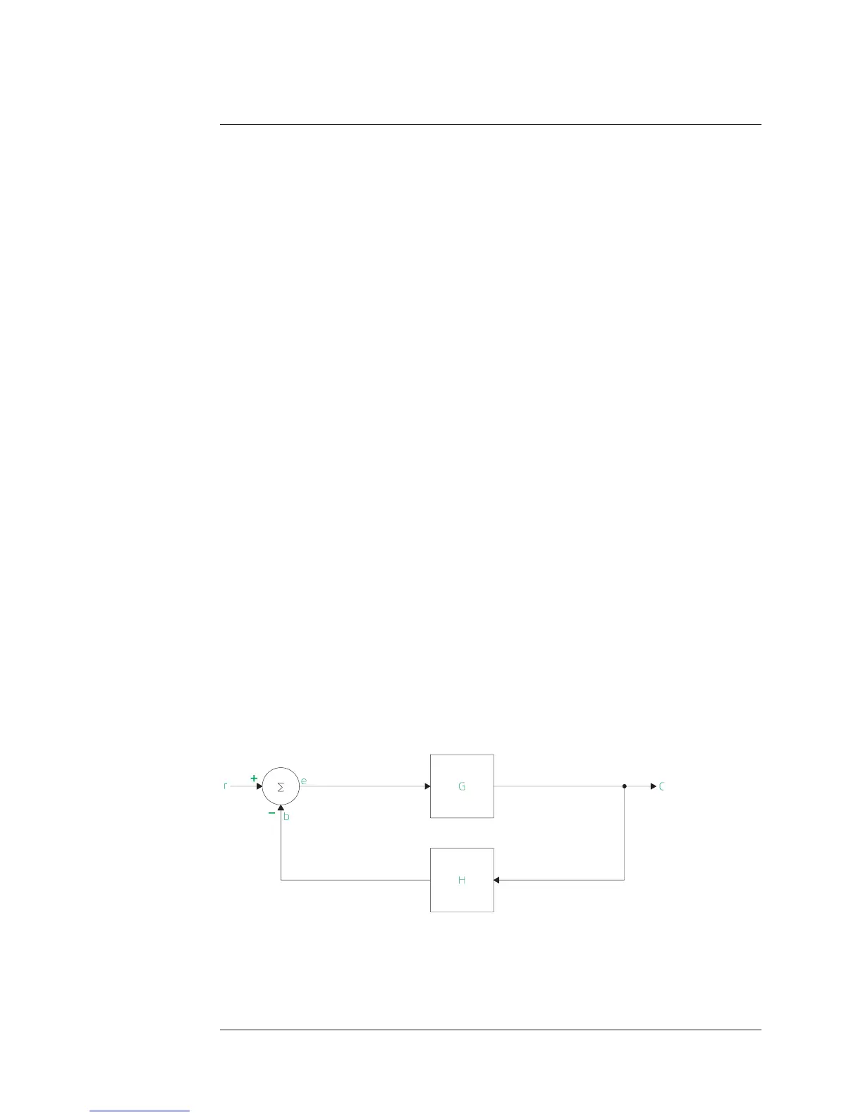
Figure 5-1 is a generic block diagram of a control or “servo” system. The
plant’s transfer function is G. The feedback transfer function is H. The goal is
to optimize closed loop performance. This is done by modifying the open loop
elements. Ideally, the control loop output (c) tracks the input (r) perfectly in
the time domain; the gain (output/input) is 1 and there is no phase lag between
input and output.
Figure 5-1
Block Diagram of a Control System
Agilent 35670A
Measuring Control Systems Operator's Guide
5-2
 Loading...


