Ref ID : ADR233B/IM/TC
Rev No. : 05
Page No. : 471 of 479
ADR233B
* Available only in M19” version
Step1. Connect all terminals as per the chart.
Step2. Adjust rated CT Secondary Current 1A/5A and Secondary Voltage as 110V.
Step3. Observe the current value from measurement menu. The actual current should
match with relay display.
Step4. Repeat the same procedure for other element.
11.4.2 Through Fault Stability Check
Ensure the below points, before carried out the through fault stability test.
• Confirm that transformer is fully isolated & discharged from both side of system.
• Confirm that the transformer HV & LV Neutral is solidly grounded.
• All shorting & test leads are properly connected.
• Confirm that the safety grounding & mains are removed from HV & LV side each time before
test.
• Confirm that the relay settings are done & all CT wiring & terminals are through.
• Trip links & LBB trip links are kept removed.
• Transformer is kept at Normal Tap.
• Test Shorting & Grounding is securely done
Transformer Data:-
Transformer Rating: MVA; Vector Group: ;
HV Nominal Voltage: kV/ V; LV Nominal Voltage: kV/ V;
HV Full load: A; LV Full load: A;
HV CTR: / A; LV CTR: / A;
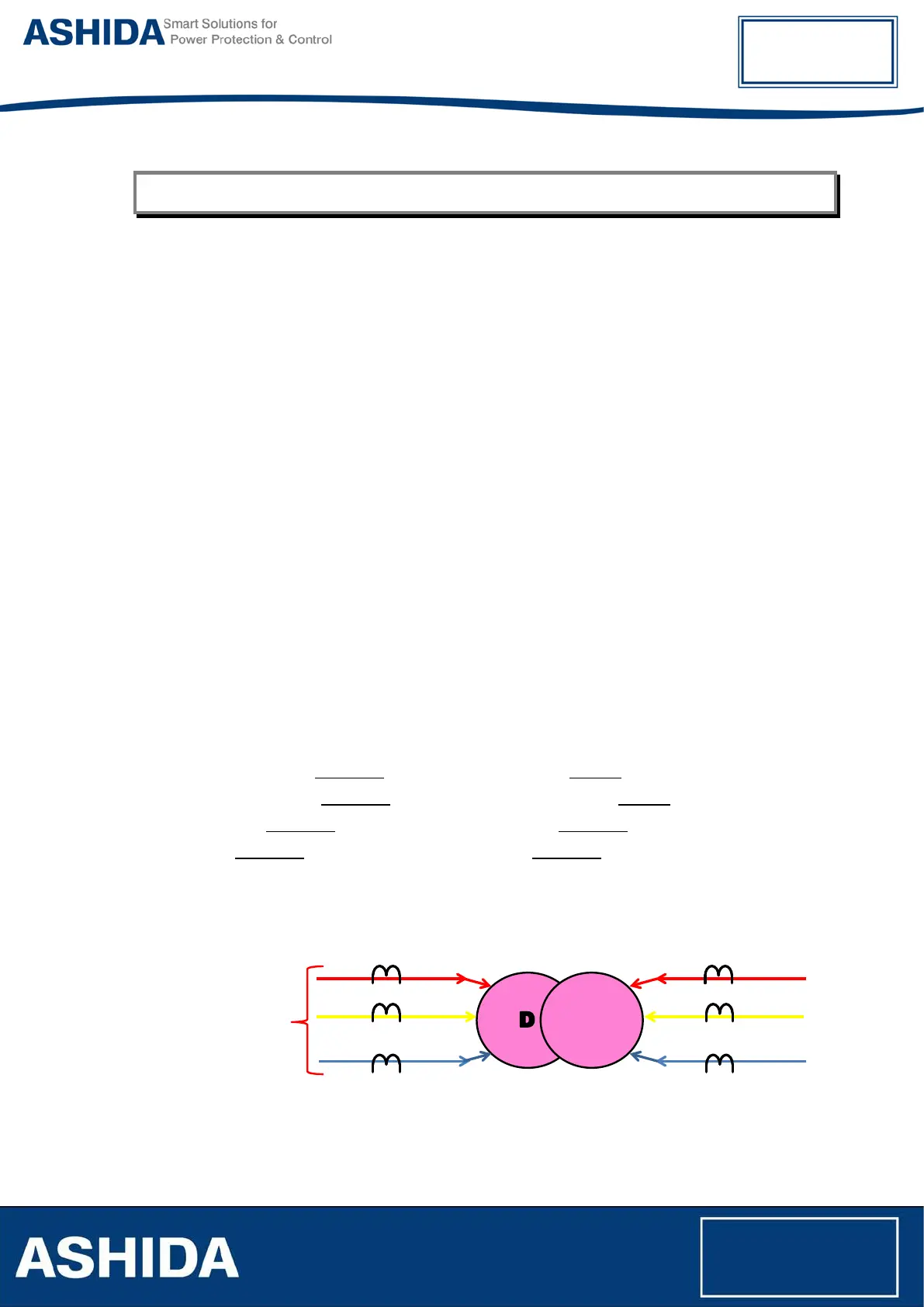
Transformer Charging:
• Apply 3 phase 440V to HV side of transformer before CT and LV side kept open.
• Measure the Primary current at CT terminal & Secondary current at relay CT terminal using
Clamp meter/ Tong tester.
• Observe & note down the primary & secondary current on Relay Measurement window.