Ref ID : ADR233B/IM/TC
Rev No. : 05
Page No. : 472 of 479
ADR233B
Relay CT Terminal Current
EF
R Y B R Y B
R Y B R Y B
Relay Display Current
HV LV
EF
Differ Current Bias Current
REF Low
Imp.
REF
High Z
W1 R W1 Y W1 B W2 R W2 Y W2 B Id R Id Y Id B Ib R Ib Y Ib B Id Ib IREF
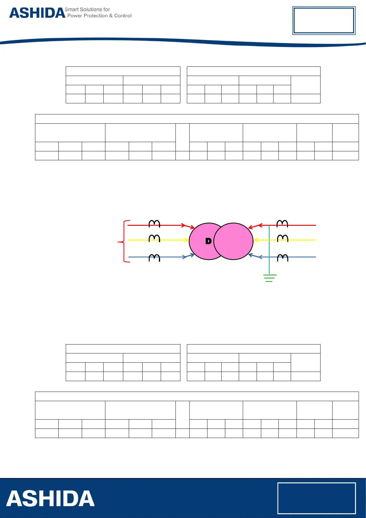
IN Zone Fault:
• Apply suitable 3 phase 440V source to HV side of transformer before CT.
• Keep R phase shorted of LV side of transformer before CT. (Keep grounded, if transformer
is grounded).
• Measure the Primary current at CT terminal & Secondary current at relay CT terminal using
Clamp meter/ Tong tester.
• Observe & note down the primary & secondary current on Relay Measurement window.
• Repeat the above procedure for Y & B phase, phase to phase and 3 phase faults.
Primary Current
Relay CT Terminal Current
HV LV
HV LV
EF
R Y B R Y B
R Y B R Y B
Relay Display Current
HV LV
EF
Differ Current Bias Current
REF Low
Imp.
REF
High Z
W1 R W1 Y W1 B W2 R W2 Y W2 B Id R Id Y Id B Ib R Ib Y Ib B Id Ib IREF