Ref ID : ADR233B/IM/TC
Rev No. : 05
Page No. : 473 of 479
ADR233B
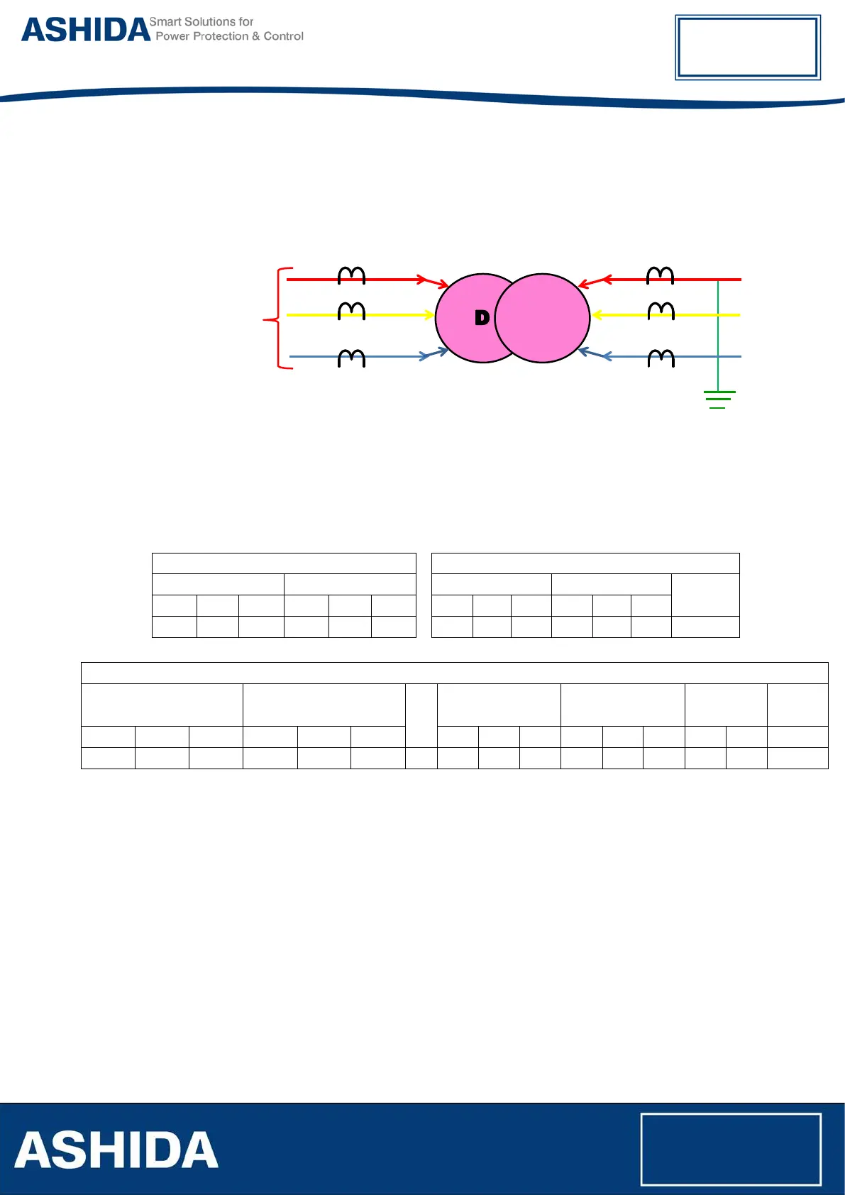
OUT Zone Fault:
• Apply suitable 3 phase 440V source to HV side of transformer before CT.
• Keep R phase shorted of LV side of transformer after CT. (Keep grounded, if transformer is
grounded).
• Measure the Primary current at CT terminal & Secondary current at relay CT terminal using
Clamp meter/ Tong tester.
• Observe & note down the primary & secondary current on Relay Measurement window.
• Repeat the above procedure for Y & B phase, phase to phase and 3 phase faults.
Primary Current
Relay CT Terminal Current
HV LV
HV LV
EF
R Y B R Y B
R Y B R Y B
Relay Display Current
HV LV
EF
Differ Current Bias Current
REF Low
Imp.
REF
High Z
W1 R W1 Y W1 B W2 R W2 Y W2 B Id R Id Y Id B Ib R Ib Y Ib B Id Ib IREF
11.4.3 Pick up and Trip Test
• Connect current source at winding 1 R-phase CT terminals 1A/5A current input terminal
• Set current setting value to 100% i.e. 1A/5A, TMS at Minimum (x0.01) value.
• Start current injector & increase current value till relay get pick up and trip. The operating
value should be within 1 to 1.1 times of set pickup value.
• Select the Curve IEC S Inverse and Set the TMS at 1.00.
• Connect the assigned trip contact to Timer.
• Set and apply 2 times current value and measure the timing on timer.
• The measured timing should be ±5% of actual timing i.e. 10.029 Sec.
• Repeat the above procedure for remaining phases and Earth Fault.