1 689 978 572 2014-06-06| Robert Bosch GmbH
Introduction | VLS 5140 | 41 en
2.4 Preparatory work by the user
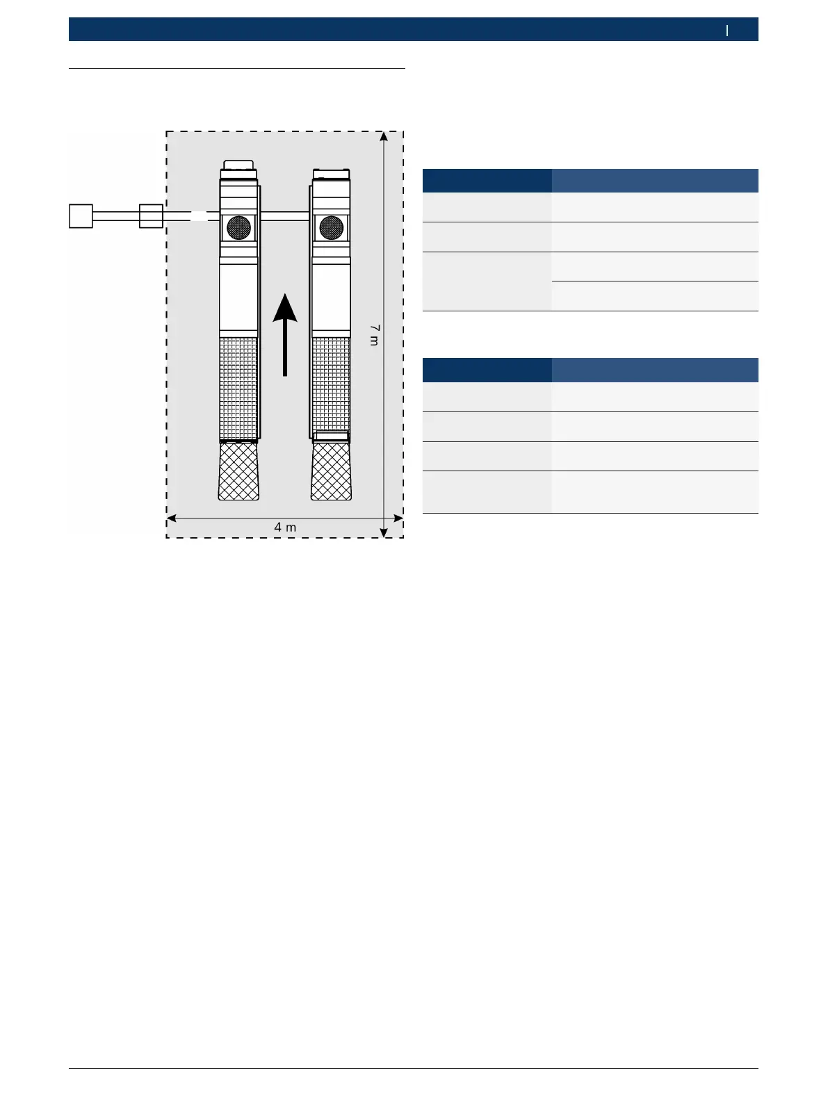
2.4.1 Required space
Fig. 2: Recommended workplace dimensions
Arrow signifies direction in which vehicle approaches
Dotted line signifies hazard zone
2.4.2 Constructing the foundations
¶ Make the foundations in consultation with Bosch
customer service or authorized service outlets.
Dimensions:
Version Min. length x width
Floor-mounted
installation
Individual footing
3,500 mm x 2,810 mm
Continuous footing
3,500 mm x 1,200 mm (2x)
Underfloor installation Individual footing
4,900 mm x 2,320 mm
Continuous footing
4,900 mm x 765 mm (2x)
Quality of concrete:
Specifications Description, value
Min. thickness
of concrete
210 mm
Quality of concrete
B 4710-1
C 20/25
Surface Horizontal and even
(gradients max. 0.5 %)
Reinforcement BSt 500 M, Q131
top: asx,y = 3.77 cm
2
/m
bottom: asx = 2.57 cm
2
/m
i See section 7 for the foundation plans.
! The base plates of the lifting platform must be
positioned as per the foundation plan.
Ground:
R The ground must comply with the general guidelines
for foundations (Eurocode 7, formerly DIN 1054).
R In the case of outdoor installation, the ground must
be frost-proof.
! The lift may not be installed outdoors. At least one
weather-proof enclosure is required.
! If the lifting platform is anchored to an existing
reinforced concrete floor, individual verification must
be provided by a structural engineer or building
expert!
! Prior to installation, the condition of the concrete and
ground must be checked by means of trial drilling.
There must be a clearance of at least 1 meter between
the lifting platform and fixed elements (e.g. wall) in all
lifting positions.
There must be sufficient space at the ends of the lifting
platform for driving vehicles on and off.
Recommended room height: min. 4 m.
i To stop vehicles colliding with the ceiling, it is
advisable to fit an overhead light barrier in buildings
with low ceilings.
 Loading...