1 689 978 572 2014-06-06| Robert Bosch GmbH
Pneumatic System | VLS 5140 | 63 en
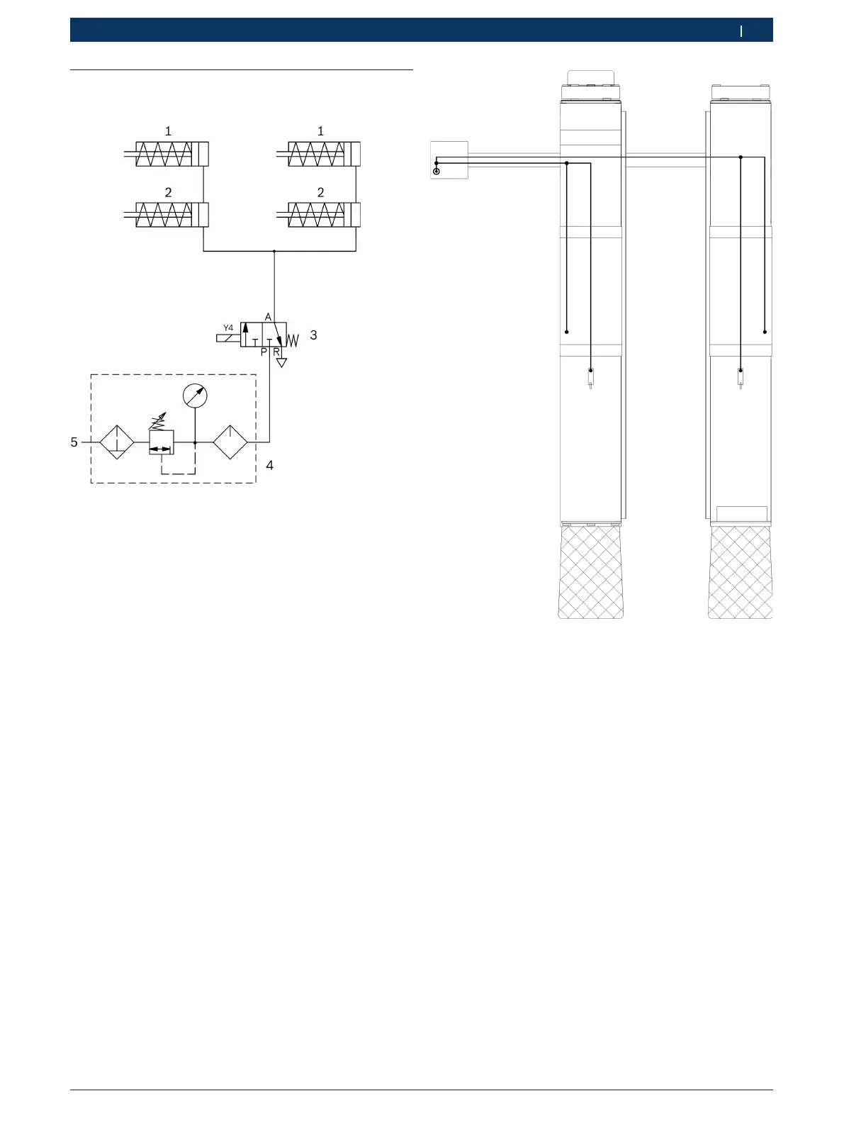
8.2 Lifting platforms with wheel-free
scissor lift
Fig. 34: Pneumatics diagram (with wheel-free scissor lift)
1 Wheel-free scissor lift release cylinder
2 Runway release cylinder
3 Pneumatic valve (3/2-way valve)
4 Compressed air service unit (customer)
5 Compressed air inlet (customer)
! Operating pressure: 8 – 10 bar. Fig. 35: Pneumatic system routing diagram
(with wheel-free scissor lift)
 Loading...