Do you have a question about the Bosch VLS 5140 and is the answer not in the manual?
Explains warning notices, structure, meaning, and symbols used.
Instructions to observe all warning notices on products and ensure legibility.
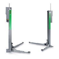
Details the installation and initial operation of Bosch lifting platforms.
Covers requirements for assembly by third parties and safety acceptance tests.
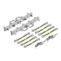
Provides details on packing units and internal transport of the lifting platform.
Outlines user responsibilities before installation, including space and foundations.
Explains terms like 'left', 'right', 'front', and 'rear' relative to vehicle direction.
Details dangers of incorrectly installed lifting platforms and installation requirements.
Instructions for positioning the runways, including safety precautions.
Guides on connecting hydraulic, pneumatic, and electrical components of the operating unit.
Describes operation using front panel controls and bypassing control system functions.
Steps for initial operation, including raising/lowering runways and bleeding hydraulics.
Procedure for bleeding hydraulic system specific to wheel-free scissor lifts.
Detailed steps for precise positioning of runway 1 and runway 2.
Guidance on installing cable ducts, drive-on ramps, and front roll-off guards.
Instructions for drilling mounting holes and anchoring the lifting platform securely.
Procedure for conducting a test run of the lifting platform at its nominal load.
Procedure for checking and correcting factory-set cut-out points for runways.
Requirements for annual safety acceptance tests by an expert.
Details warranty conditions dependent on proper safety acceptance and Bosch parts.
Checks required for grounding conductors after installation, repairs, or modifications.
Provides overall dimensions for the VLS 5140 model in millimeters.
Provides overall dimensions for the VLS 5140 A model in millimeters.
Provides overall dimensions for the VLS 5140 L model in millimeters.
Provides overall dimensions for the VLS 5140 LA model in millimeters.
Details foundation plans for floor-mounted installations, including individual footing.
Provides foundation plan details for continuous footing floor-mounted installations.
Details foundation plans for underfloor installation types.
Details foundation plans for underfloor installation with individual footing.
Details foundation plans for underfloor installation with continuous footing.
Details foundation requirements for recesses for 3D wheel alignment units.
Diagram and explanation of the pneumatic system for platforms without wheel-free scissor lift.
Diagram and explanation of the pneumatic system for platforms with wheel-free scissor lift.
Hydraulic diagrams for platforms without wheel-free scissor lift, detailing components.
Hydraulic diagrams for platforms with wheel-free scissor lift, detailing components.
Procedure for safely lowering a raised vehicle using the emergency function.
Presents the electrical circuit diagram for the power supply of the VLS 5140.
Shows the circuit diagram for the control board and associated components.
Illustrates the circuit diagram for the lift and lower button functions.
Depicts the circuit diagram related to the solenoid valves used in the system.
| Brand | Bosch |
|---|---|
| Model | VLS 5140 |
| Category | Lifting Systems |
| Language | English |