1 689 978 572 2014-06-06| Robert Bosch GmbH
60 | VLS 5140 | Foundation Plans en
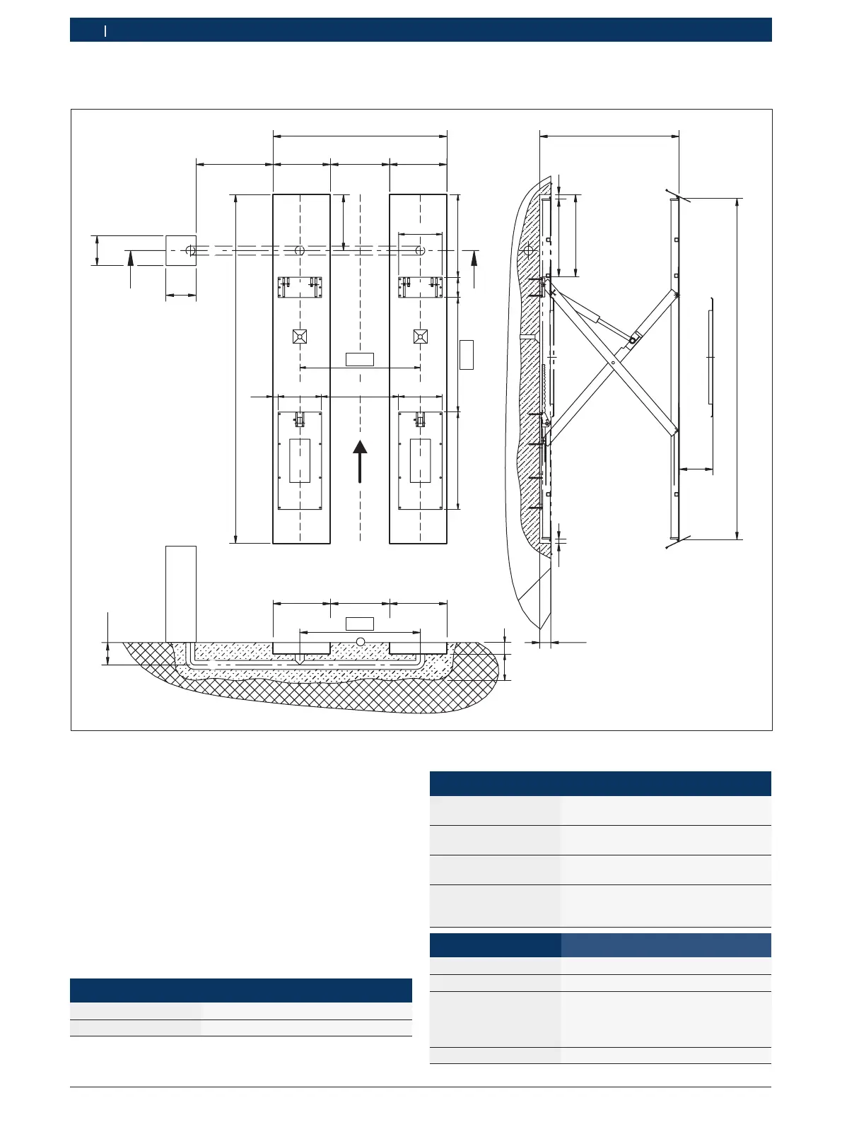
7.2.2 Continuous footing
4800
450
2100
170/220
400
400
A
A
min. 1000
max. 2250
2320
790 765
4900
750
50
1088
1038
50
270
1530
1300
580
580
1088
580 1030
1610
65
765
300
790 765765
1610
min.
210
Version 1.0
A–A
Ø120
Fig. 29: Foundation plan 3 (all dimensions in mm. Arrow = direction in which vehicle approaches)
(1) Before starting construction work, it must be
ensured that the most up-to-date version of the
foundation plan is available.
(2) It is not possible to use an axle lift in conjunction
with continuous footing.
(3) The four base plates must be perfectly level and
even. The maximum height deviation is 5 mm. Levelling
is required!
(4) Front drive-on flaps are optional. The standard
version is equipped with a rigid roll-off guard.
(5) Adequate drainage must be ensured.
(6) Connections in the operating unit
Mains connection 3/NPE; 400 V; 50 Hz
Compressed air 8 – 10 bar (provide service unit)
(7) Use a conduit with Ø 120 mm for the connecting
cables.
(8) Concrete quality
Min. thickness
of concrete
210 mm
Quality of concrete
B 4710-1
C 20/25
Surface Horizontal and even
(gradients max. 0.5 %)
Reinforcement BSt 500 M, Q131
top: asx,y = 3.77 cm
2
/m
bottom: asx = 2.57 cm
2
/m
(9) Lifting platform Recess depth
VLS 5140 170 mm
VLS 5140 A 220 mm
VLS 5140 L
Secondary lift
at floor level:
170 mm
220 mm (compensating elements
are required in front of and behind
the secondary lift)
VLS 5140 LA 220 mm
 Loading...