1 689 978 572 2014-06-06| Robert Bosch GmbH
50 | VLS 5140 | Installationen
3.9.3 Leveling the lower position
1. Press the "Lower" button (u) and fully lower the
runway.
2. Place runway under load (medium-sized vehicle)
3. Check the runway:
$ There should be a clearance of approx. 1 cm
between the lower edge of the runway and the
foundations.
$ Each runway must be balanced longitudinally and
transversely.
! A leveling device is required for precise checking of
the alignment.
If necessary:
4. Raise the runway.
5. Adjust the height of any incorrectly set rubber
buffers.
Fig. 19: Height-adjustable rubber buffer
6. Return to step 1.
Once all rubber buffers have been correctly adjusted:
7. Raise the runway.
8. Re-tighten the nuts on all rubber buffers.
3.10 Setting the cut-out points
! The cut-out points set in the factory must be
checked during initial operation and corrected if
necessary.
3.10.1 Cut-out points
The lifting platform is controlled and monitored using
an electronic control system. The cut-out points for the
runways can be determined by the user himself.
Cut-out point Position
Upper cut-out
point
The top edge of the runway is located max.
1,830 mm above the foundations.
"Foot protection"
safety level
The lower edge of the runway is located
200 – 250 mm above the foundations.
Lower cut-out
point
Runway is resting with rubber buffers on
the foundations.
i The stored values are retained even with the power
supply switched off.
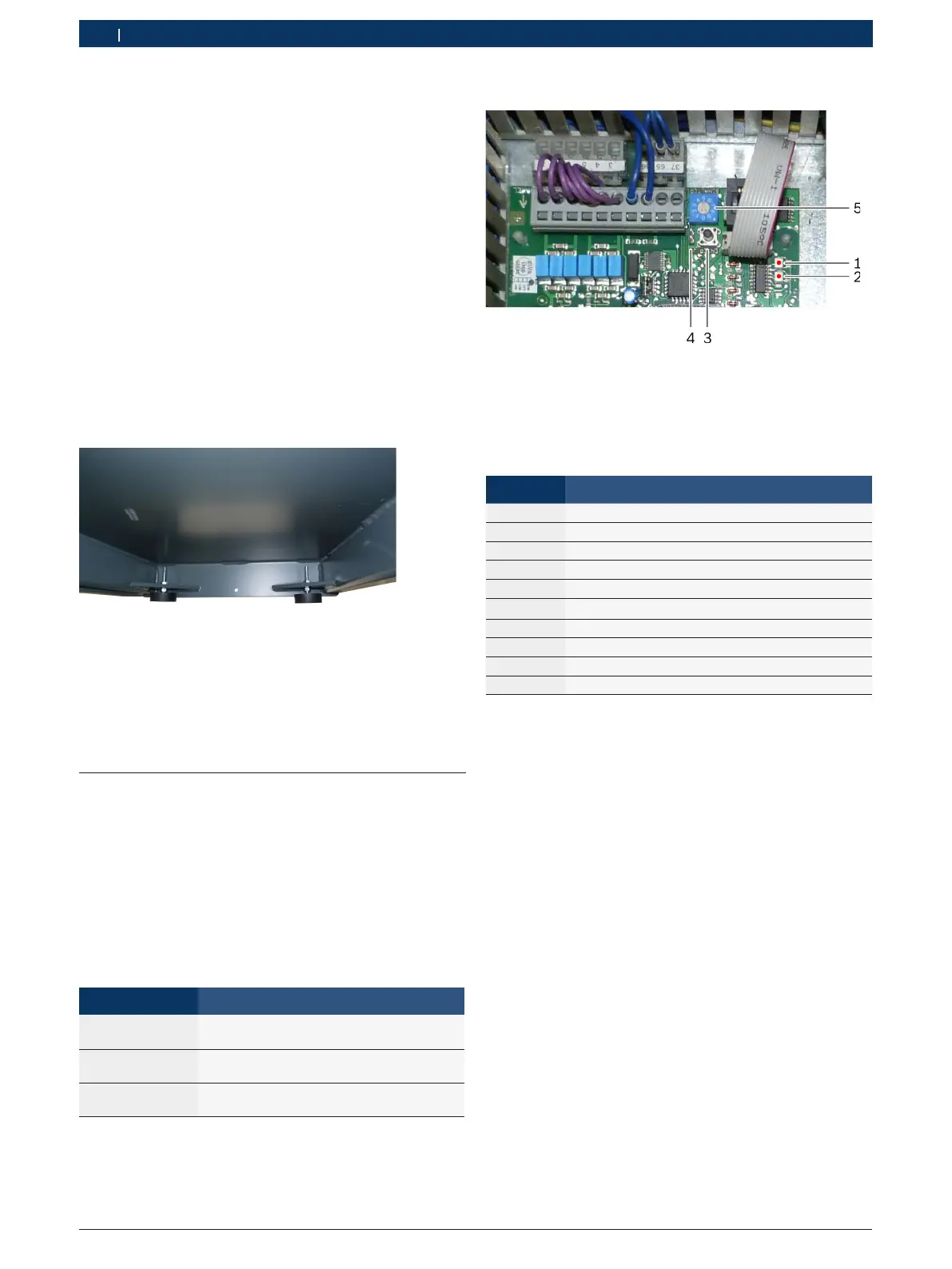
3.10.2 Controls on the control board
Fig. 20: Controls on the control board
1 LED for runway 1 (red/green)
2 LED for runway 2 (red/green)
3 Confirmation button (ENTER)
4 Jumper J1 (standard position: open)
5 Program selector switch (see table)
Program Action
0 Operation basic setting
1 Set lower cut-out point
2 Compensate difference in runway height
3 Set upper cut-out point
4 Positioning run
5 Positioning run
6 Set "Foot protection" safety level
7 Test: displacement sensor
8 Test: contacts, horn, data EEPROM
9 Read out fault memory
3.10.3 Setting the cut-out points
! There is no automatic final cut-off for the adjustment
processes. Observe the overrun of approx. 5 mm.
¶ Check the requirements:
$ Runways are level.
$ Rubber buffers are adjusted.
$ Displacement sensors are correctly set.
Set lower cut-out point
1. Set the program selector switch to "1".
2. Press the confirmation button.
Both LEDs light up green.
Program 1 is selected.
3. Fully lower the runway.
4. Press the confirmation button.
Both LEDs flash green.
"The lower cut-out point is now saved
 Loading...