1 689 978 572 2014-06-06| Robert Bosch GmbH
44 | VLS 5140 | Installationen
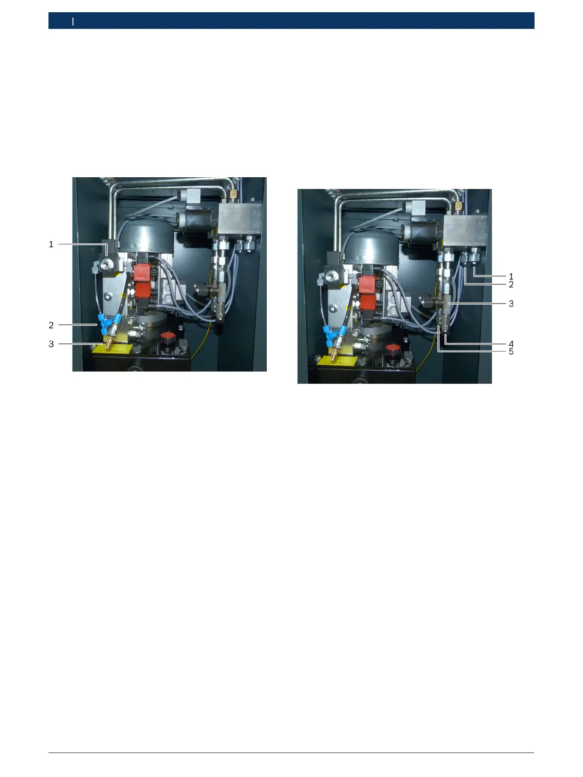
3.4.2 Connecting the pneumatic lines
i Refer to section 8 for the pneumatics diagram.
1. Route the pneumatic lines from the lifting platform
into the inside of the operating unit.
2. Connect the pneumatic lines from the lifting
platform to the two pneumatic outlets (2).
3. Connect the user’s compressed air supply to the
pneumatic inlet (3).
Fig. 7: Pneumatic connections
1 Exhaust air
2 Pneumatic outlet (coupling for 2 lines)
3 Pneumatic inlet
! Set the user's compressed air service unit to
anoutlet pressure of 8–10 bar.
3.4.3 Connecting the hydraulic lines
i Refer to section 9 for the hydraulics diagram.
1. Route the hydraulic lines from the lifting platform
into the inside of the operating unit.
2. Connect the hydraulic lines from the runways to the
hydraulic connections (1, 2).
3. For lifting platforms with wheel-free scissor lift:
Connect the hydraulic lines of the wheel-free scissor
lift to the hydraulic connections (4, 5).
Fig. 8: Hydraulic connections
1 Connection for runway 1
2 Connection for runway 2
3 Throttle non-return valve for wheel-free scissor lift
4 Connection for wheel-free scissor lift 1
5 Connection for wheel-free scissor lift 2
 Loading...