1 689 978 572 2014-06-06| Robert Bosch GmbH
Installation | VLS 5140 | 45 en
3.4.4 Electrical connection
! The electrical cables must be connected by a
qualified electrician. This conforms with VDE 0100.
i For the wiring diagrams, see section 10.
1. Undo and remove the screws on the left and right at
the top of the operating unit.
2. Remove the upper cover on the operating unit. You
cannot access the electronic control system of the
lifting platform.
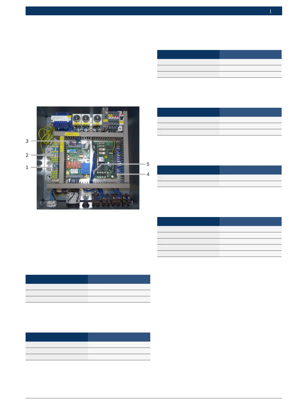
Fig. 9: Electrical connections in the operating unit
1 Mains supply
2 Runway lighting
3 Potentiometers 1 and 2
4 Light barrier 1
5 Light barrier 2
Potentiometer 1 (runway 1)
¶ Route the cables for potentiometer 1 through a small
strain relief and connect to position (3).
Cable Terminal
Brown 3
White 4
Green 5
Potentiometer 2 (runway 2)
¶ Route the cables for potentiometer 2 through a small
strain relief and connect to position (3).
Cable Terminal
Green 6
White 7
Brown 8
Light barrier 1
¶ Route the cable for light barrier 1 through a small
strain relief and connect to position (4).
Cable Terminal
Brown 1
Blue 2
Black 3
Light barrier 2
¶ Route the cable for light barrier 2 through a small
strain relief and connect to position (5).
Cable Terminal
Brown 64
Blue 65
Black 66
Runway lighting
¶ Route the cables for the runway lighting through four
small strain reliefs and connect to position (2).
Cable Terminal
Black Gray (phase)
Black Blue (neutral conductor)
Mains supply
¶ Route the cable for the mains supply through the
large strain relief and connect to position (1).
Cable Terminal
Phase L1 Gray (L1)
Phase L2 Gray (L2)
Phase L3 Gray (L3)
Neutral conductor Blue (N)
Grounding conductor Yellow/green (PE)
Grounding conductor
¶ Check the grounding conductor.
 Loading...