100-412-234 REV. 06 33
Test Scale
The magnification of the power bar on the front panel of the power
supply, useful for lower-power applications that want a more
accurate (but smaller) scale.
Time Mode Terminates the ultrasonics at a user-specified time.
Timeout
A time at which the ultrasonic energy terminates if the main
control parameter has not been reached.
Trig Delay
Trigger Delay. A user-programmable time delay between
engagement of the trigger switch and start of ultrasonics and
ramping of force to the weld force.
Trigger
Trigger force triggers the start of ultrasonics based on a set force
level. Trigger distance triggers the start of ultrasonics based on a
set travel distance. Trigger distance doesn’t consider force when
used.
Trigger Beeper An audible signal sounded when the trigger is made.
Upper Limit
Switch (ULS)
A switch when activated indicates the actuator is in the home
position.
UPS Power supply module.
USB Copy Now
Allows a PDF copy of weld history, event history, weld setup, and
User ID table to be copied to a USB flash drive. The flash drive
must be installed for this function to appear.
USB Streaming
Data Setup
Allows real time recording of weld data and graphs to a USB flash
drive. The weld data and graphs can be viewed on a PC using the
Branson Weld History Utility Program.
User I/O
The User I/O is used to configure actuator inputs and outputs. This
menu can only be entered when the welder is not in a weld cycle.
User ID Setup Add and modify users allowed access to the power supply.
User-defined
Limits
For process resultants, where - is the user-defined lower limit, and
+ is the user defined upper limit:
• -/+ S/R Energy: The energy reached during the weld.
• –/+ Force: The force at the end of the weld.
• -/+ S/R Freq: The peak frequency reached during a weld.
• -/+ S/R Power: The peak power as a percentage of the maximum
reached during the weld.
• -/+ S/R Abs D: The absolute distance reached during the weld from the
Upper Limit Switch.
• -/+ S/R Col D: The collapse distance reached from trigger to end of
weld.
• -/+ S/R Trg D: The distance at which the trigger occurred.
• -/+ S/R Time: The weld time reached during the weld.
Velocity Graph A graph of the velocity of the actuator during weld.
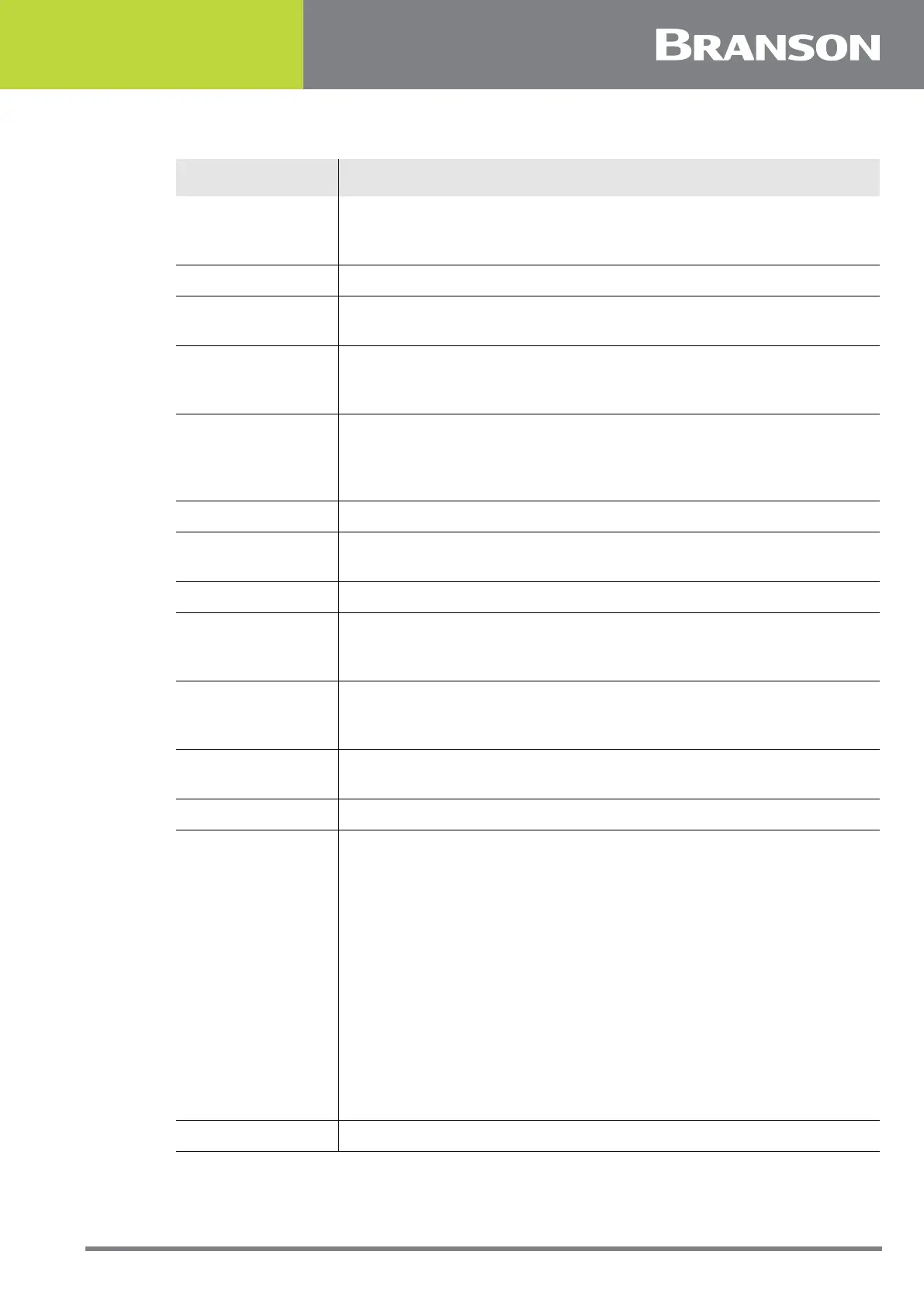
Table 2.3 Glossary of Terms
Name Description